Low-energy-consumption and environmental-friendly grain dryer

An environmentally friendly technology for grain dryers, applied in grain drying, drying machines, and drying solid materials, etc., can solve the problems of grain dryer dust, surrounding environment impact, and large power consumption, etc., to shorten the drying process and ensure Effect of grain quality and energy consumption reduction

Pending Publication Date: 2019-11-26
ANHUI CHENYU MECHANICAL +1
View PDF7 Cites 0 Cited by
  • Summary
  • Abstract
  • Description
  • Claims
  • Application Information

AI Technical Summary

Problems solved by technology

[0003] Grain dryers currently on the market mainly include chassis, grain discharge layer, drying layer, slowing layer, hoist, upper and lower conveying augers, grain spreading mechanism, control system, exhaust fan and other parts, among which the upper and lower conveying The auger, grain spreading mechanism, exhaust fan, hoist, etc. all need motors to drive, and during the working process of the grain dryer, these motors need to work continuously, which requires a lot of power consumption and high energy consumption
Furthermore, the hot air used to dry the grain enters through the air inlet pipe and flows through the drying layer, and then is directly discharged from the air outlet pipe. A large amount of dust attached to the hot air from the grain will be directly discharged into the air, which will cause dust around the grain dryer. Diffuse, affecting the surrounding environment

Method used


Image

  • Low-energy-consumption and environmental-friendly grain dryer
  • Low-energy-consumption and environmental-friendly grain dryer
  • Low-energy-consumption and environmental-friendly grain dryer

Examples


Embodiment Construction

[0023] The present invention will be described in further detail below in conjunction with the accompanying drawings.

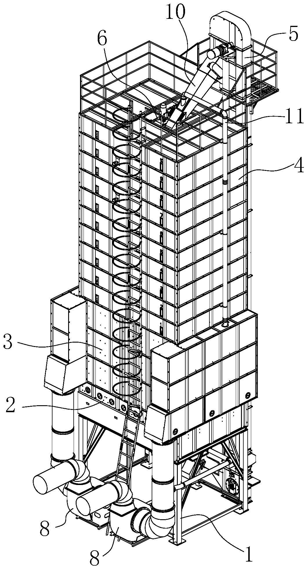
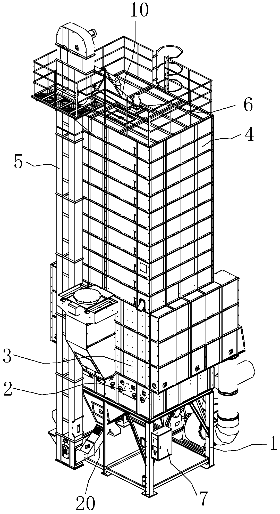
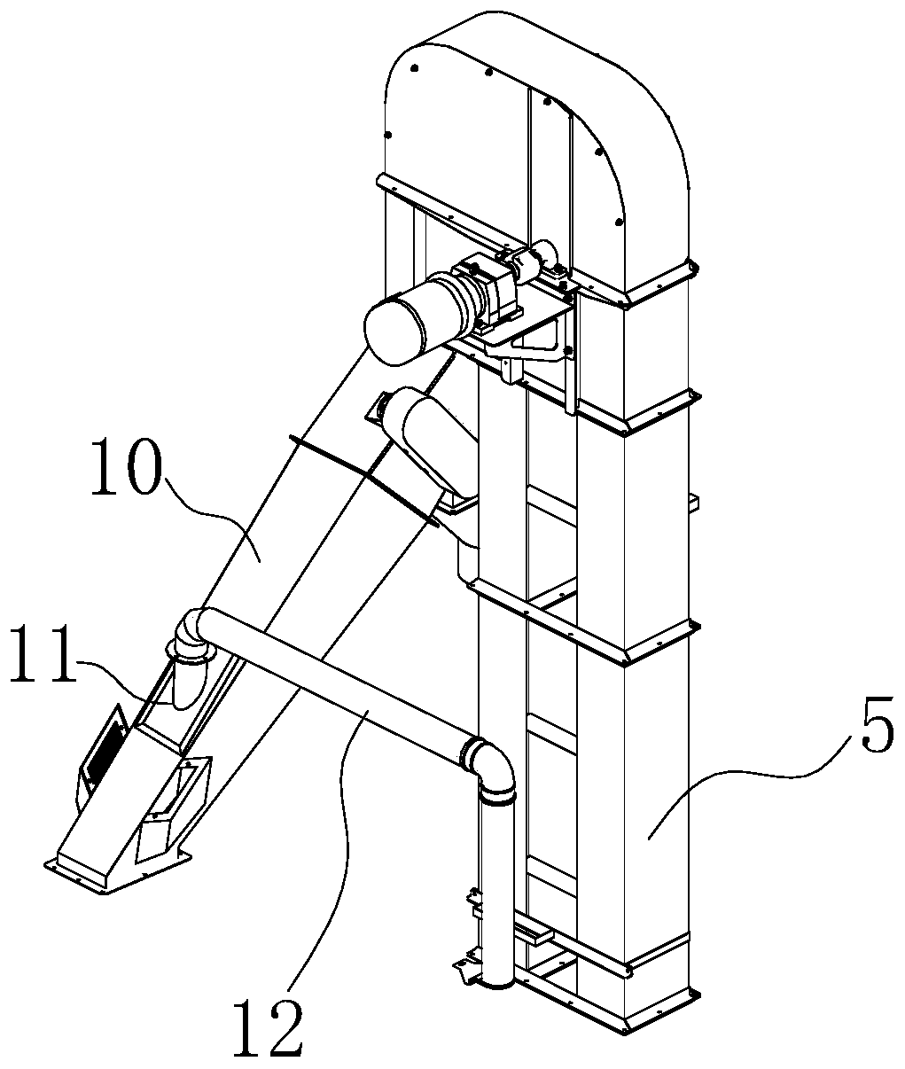
[0024] A low energy consumption and environment-friendly grain dryer, comprising a chassis 1, a grain discharge layer 2, a drying layer 3, a slowing layer 4, a hoist 5, a grain spreading mechanism 6, a control system 7, and an exhaust fan 8, characterized in that: An upper flow pipe 10 is placed obliquely between the top of the elevator 5 and the grain spreading mechanism 6, and a downflow pipe 20 is arranged obliquely between the bottom of the grain discharge layer 2 and the bottom of the elevator 5, and the upper flow pipe 10 will be lifted to the top by the elevator 5. The grain diversion is diverted in the grain spreading mechanism 6, and the downflow pipe 20 diverts the grain discharged from the grain discharge layer 2 to the bottom of the hoist 5 for circulation. The core of the present invention is to replace the traditional upper and lower auger conve...


PUM


Abstract

The invention discloses a low-energy-consumption and environmental-friendly grain dryer. The dryer comprises an underframe, a grain discharging layer, a drying layer, a tempering layer, a hoist, a grain spreading mechanism, a control system and an exhaust fan, wherein an upflow pipe is arranged obliquely between the top end of the hoist and the grain spreading mechanism, a downflow pipe is arranged obliquely between the lower part of the grain discharging layer and the bottom of the hoist, the grain hoisted to the top by the hoist is diverted to the grain spreading mechanism by the upflow pipe, and the grain discharged by the grain discharging layer is diverted to the bottom of the hoist by the downflow pipe for circulation. The upflow and downflow pipes replace a traditional upper and lower auger conveying mode, thus effectively avoiding the physical crushing caused by the extrusion of the grain during the conveying of upper and lower augers, improving the integrity of the grain and ensuring the quality of the dried grain. Furthermore, as the traditional upper and lower conveyor augers are eliminated, the use of two auger motors is avoided, the power consumption of the machine isgreatly reduced, and energy consumption is reduced.

Description

technical field [0001] The invention relates to the technical field of grain drying equipment, in particular to a low energy consumption and environment-friendly grain dryer. Background technique [0002] Grain dryers are used to dry granular grains such as rice, wheat, corn, soybeans, and rapeseed. With the rapid development of modern agriculture, the output of various grain crops is increasing, making the market demand for grain dryers Also rising, grain dryer has become an important part of the modernization of grain production. [0003] Grain dryers currently on the market mainly include chassis, grain discharge layer, drying layer, slowing layer, hoist, upper and lower conveying augers, grain spreading mechanism, control system, exhaust fan and other parts, among which the upper and lower conveying The auger, grain spreading mechanism, exhaust fan, hoist, etc. all need motors to drive, and during the working process of the grain dryer, these motors need to work continu...

Claims


Application Information

Patent Timeline
IPC IPC(8): F26B17/00F26B21/00F26B25/00A23B9/08
CPCA23B9/08F26B17/00F26B21/00F26B25/00F26B2200/06
Inventor 谢尚臻段贤伍何超波吴正浩杨健吴然然李林鹤常志强管耀文潘文超吴运生朱黄富
Owner ANHUI CHENYU MECHANICAL
Why Eureka
Try Eureka