Optical path structure

A technology of light path and light, which is applied in the direction of material analysis, measuring devices, and instruments through optical means, can solve the problems of complex light path structure and low light fusion efficiency, and achieve high light efficiency, compact cavity structure design, and easy processing and adjust the effect

Pending Publication Date: 2019-11-26
METTLER TOLEDO INSTR SHANGHAI +1
View PDF0 Cites 0 Cited by
  • Summary
  • Abstract
  • Description
  • Claims
  • Application Information

AI Technical Summary

Problems solved by technology

[0004] The technical problem to be solved by the present invention is to overcome the defect that the optical path structure of the sensor in the prior art is too complicated and the light fusion efficiency is low due to different optical paths, and provide a new optical path structure, which realizes the optical path through a compact cavity structure design Consistency and Light Fusion

Method used


Image

  • Optical path structure
  • Optical path structure
  • Optical path structure

Examples


Embodiment 1

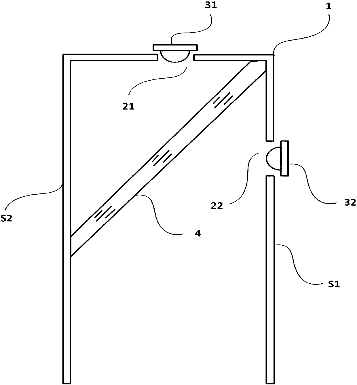
[0050] Such as figure 1 As shown, the optical path structure in this embodiment includes a cuboid cavity 1, one end of the cavity 1 is open, and a through hole 21 is arranged on the end surface of the other end, and the red LED 31 is arranged at the through hole 21, and the light emitted by the LED 31 It is emitted through the through hole 21 toward the opening of the cavity 1 .

[0051] The side S1 of the four sides of the cavity 1 is provided with a through hole 22 , and the blue LED 32 is arranged at the through hole 22 , and the light emitted by the LED 32 is emitted to the side S2 through the through hole 22 .

[0052] In cavity 1 such as figure 1 The dichroic mirror 4 is arranged as shown, and the dichroic mirror 4 described in this embodiment can allow the red light emitted by the LED31 to directly pass through the dichroic mirror 4, but the blue light emitted by the LED32 is reflected at 90°, and the red light directly transmitted Combined with the blue light reflect...

Embodiment 2

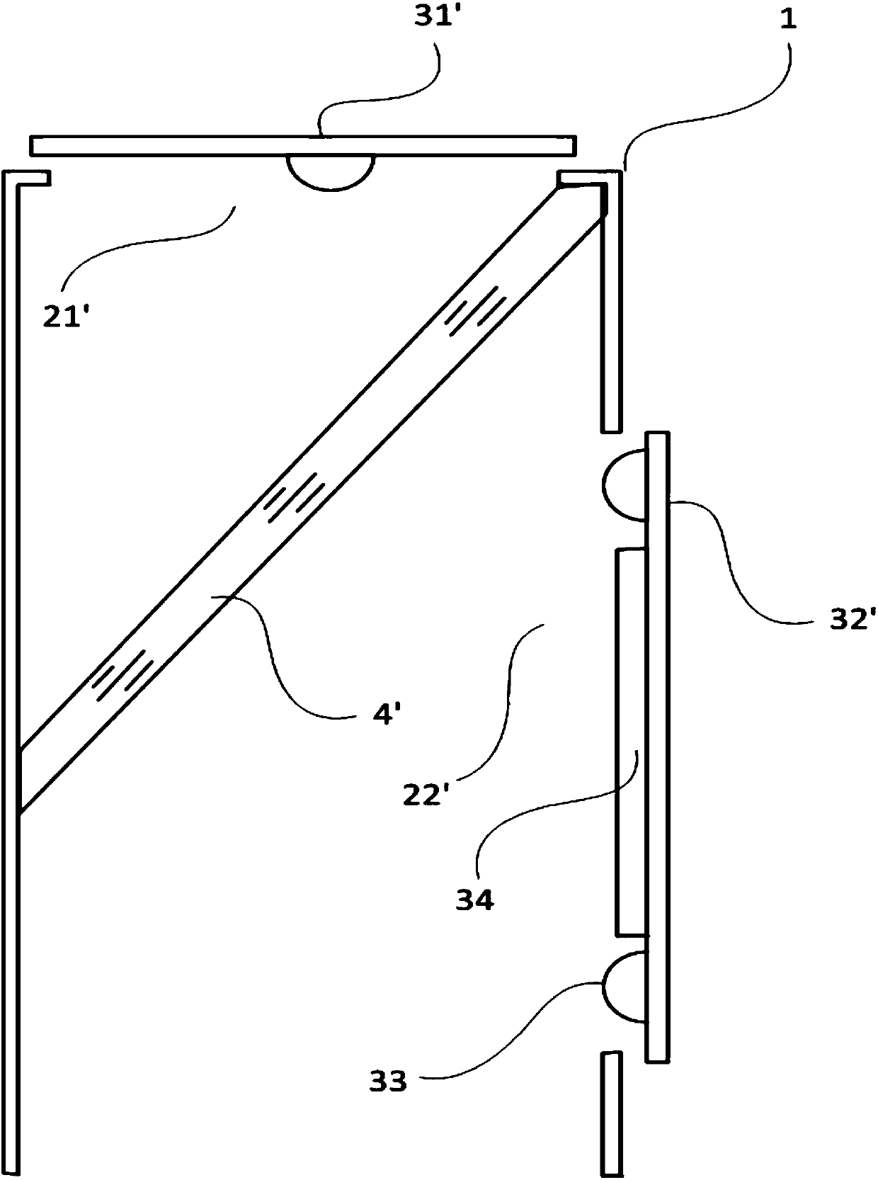
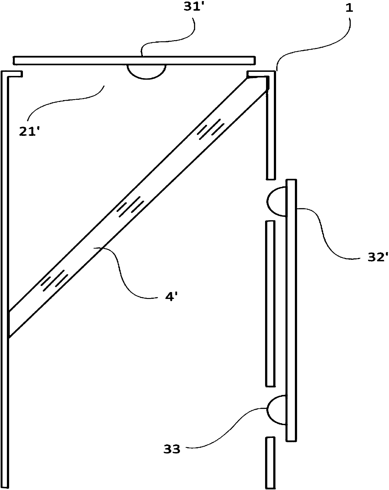
[0056] Such as figure 2 As shown, the cavity 1 in this embodiment is a cylinder, one end of the cavity 1 is open, and a strip-shaped notch 21' is provided on the end surface of the other end, the LED board 31' covers the notch 21', and the LED The light emitted by the plate 31 ′ is emitted toward the opening of the cavity 1 through the notch 21 ′.

[0057] A strip-shaped notch 22' is provided on the side of the cavity 1, and the LED board 32' covers the notch 22', and the light emitted by the LED board 32' is emitted to the other side of the cavity opposite to the notch 22' through the notch 22'.

[0058] In this embodiment, a photodiode 33 is also arranged on the LED board 32', and the photodiode 33 faces the notch 22' to collect the light intensity in the cavity.

[0059]Moreover, a light blocking member 34 is arranged between the second LED 22 and the photodiode 33, so that the light emitted by the second LED 22 cannot directly irradiate the photosensitive surface of the ...

Embodiment 3

[0064] Such as Figure 4 As shown, the difference between this embodiment and Embodiment 2 lies in that a lens 5 is provided at the opening of the cavity 1 in this embodiment, and the lens 5 collimates and converts the combined light beams into parallel light or condenses light.

[0065] In a modified example of this embodiment, the lens may be a lens group to convert the combined light beam into parallel light or to condense light.

[0066] Such as Figure 5 In another embodiment shown, the lens 5 is inlaid on the threaded connector 6, the threaded connector matches the threads at the opening of the cavity 1, and the threaded connector 6 can be screwed and fixed at the opening.

[0067] In another embodiment of this embodiment, the lens or the lens group is inserted into the opening of the cavity by buckling, and can be removed from the opening of the cavity manually or with the aid of tools. The fixing of the lens lens in the opening of the cavity can be realized more conv...


PUM


Abstract

The invention discloses an optical path structure. The optical path structure comprises a cavity with an opening at one end, wherein a first through hole or a first notch is formed in the other end, relative to the opening, of the cavity, a first LED is arranged at the other end, relative to the opening, of the cavity, and light rays emitted from the first LED are incident into the cavity by meansof the first through hole or the first notch; a second through hole or a second notch is formed in the side surface of the cavity, a second LED is arranged on the side surface of the cavity, and light rays emitted from the second LED are incident into the cavity by means of the second through hole or the second notch; the cavity is further internally provided with a spectroscope or a dichroscope;the light rays emitted from the first LED directly pass through the spectroscope or the dichroscope and are emitted out from the opening of the cavity; the light rays emitted from the second LED arereflected by means of the spectroscope or the dichroscope and fused with the light rays emitted from the first LED; and the optical distances from the light rays emitted by the first LED and the lightrays emitted by the second LED to the spectroscope or the dichroscope are the same. The optical path structure realizes the consistency of the optical distances and the fusion of the light rays by designing the compact cavity structure.

Description

technical field [0001] The invention relates to an optical path structure, in particular to an optical path structure in a sensor. Background technique [0002] In a chromaticity sensor or a turbidity sensor, an optical path is required to fuse two paths of light with different wavelengths. However, in the prior art, in the process of light fusion, it is necessary to adjust the light transmission direction through a combination of multiple sets of prisms for different light sources. In this way, the light is fused into the same optical path, but this design makes the light emitted by different light sources have different optical path lengths before fusion, which affects the effect of light fusion. And this design uses relatively many prisms and / or lenses, making the structure of the optical path complex. [0003] In other designs, optical fibers are used to transmit light from different light sources, for example, Y-shaped optical fibers are used to combine and output ligh...

Claims


Application Information

Patent Timeline
Patent Type & Authority Applications(China)
IPC IPC(8): G01N21/01
CPCG01N21/01
Inventor 王长林朱虹王冯晋徐敏王聪
Owner METTLER TOLEDO INSTR SHANGHAI
Why Eureka
Try Eureka