Piezoelectric accelerometer
An accelerometer and piezoelectric technology, applied in the field of piezoelectric accelerometers, can solve the problems of torsional deformation of accelerometers, poor consistency, affecting the accurate measurement of accelerometers, etc., achieve high dynamic bandwidth, reduce torsional deformation, and enhance stability sexual effect
- Summary
- Abstract
- Description
- Claims
- Application Information
AI Technical Summary
Problems solved by technology
Method used
Image

Examples
Embodiment 1
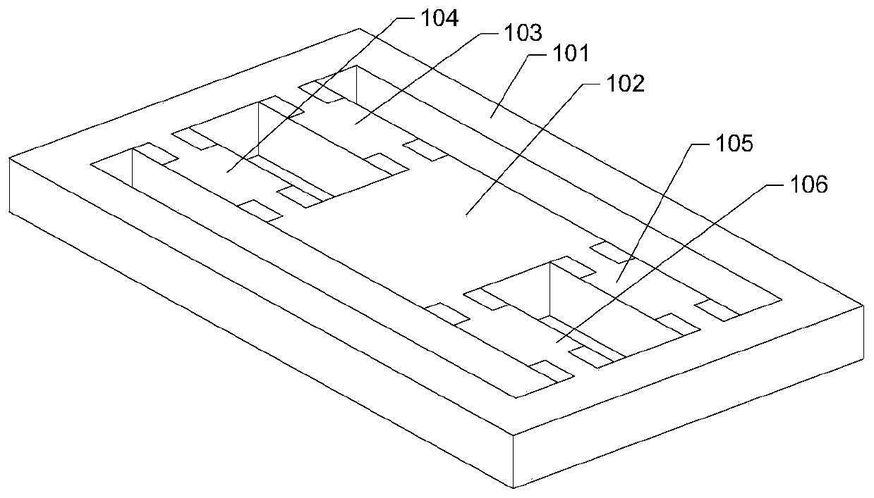
[0019] see figure 1 , a piezoelectric accelerometer, comprising a rectangular frame 101, a cuboid mass block 102 is arranged in the rectangular frame 101, and the mass block 102 is fixed with a beam one 103, a beam two 104, and a beam three on a group of sides parallel to each other 105 and beam 4 106, beam 1 103, beam 2 104, beam 3 105 and beam 4 106 are all fixedly connected to the inner wall of the rectangular frame 101 at the end away from the mass block 102; beam 1 103 and beam 2 104 are mutually symmetrical and located at the same On the side, beam three 105 and beam four 106 are symmetrical to each other and are located on the other side parallel to the side of beam one 103. There is a gap between beam one 103 and beam two 104, and between beam three 105 and beam four 106. There are gaps, beam 1 103 and beam 3 105 are symmetrical to each other, beam 2 104 and beam 4 106 are mutually symmetrical; beam 1 103, beam 2 104, beam 3 105 and beam 4 106 are all provided with pie...
Embodiment 2
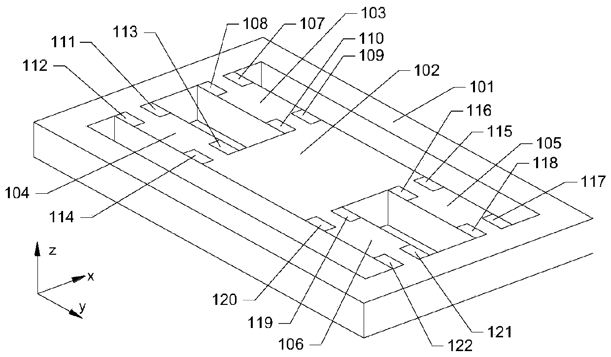
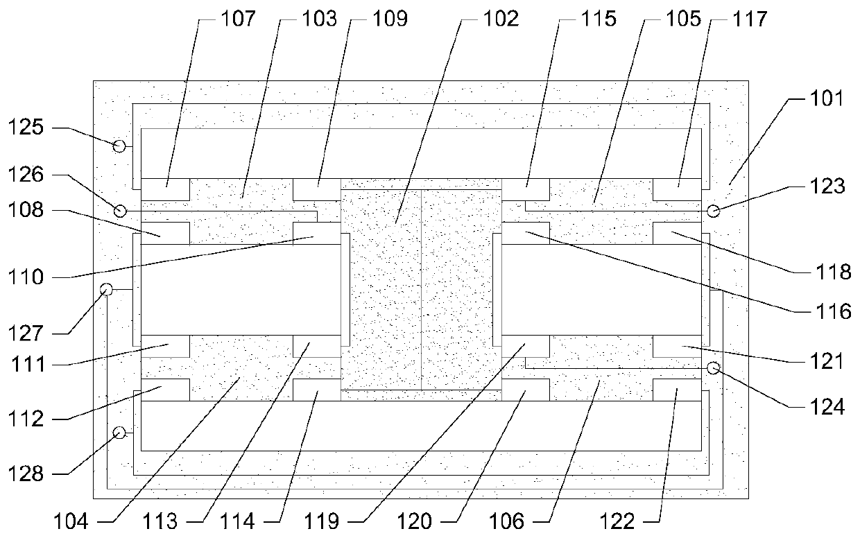
[0027] Such as figure 2 and image 3 As shown, a piezoelectric accelerometer includes a rectangular frame 101, a cuboid mass block 102 is arranged in the rectangular frame 101, and the mass block 102 fixes a beam one 103, a beam two 104, and a beam two 104 on a group of mutually parallel sides. Beam 3 105 and beam 4 106, beam 1 103, beam 2 104, beam 3 105 and beam 4 106 are all fixedly connected to the inner wall of the rectangular frame 101 at the ends far away from the mass block 102; beam 1 103 and beam 2 104 are mutually symmetrical and located On the same side, beam three 105 and beam four 106 are symmetrical to each other and are located on the other side parallel to the side where beam one 103 is located. There is a gap between beam one 103 and beam two 104, and between beam three 105 and beam four 106 There is a gap left, beam one 103 and beam three 105 are symmetrical to each other, beam two 104 and beam four 106 are mutually symmetrical; A metal electrode is respe...
Embodiment 3
[0037] Such as Figure 4 and Figure 5 As shown, a piezoelectric accelerometer includes a rectangular frame 101, a cuboid mass block 102 is arranged in the rectangular frame 101, and the mass block 102 fixes a beam one 103, a beam two 104, and a beam two 104 on a group of mutually parallel sides. Beam 3 105 and beam 4 106, beam 1 103, beam 2 104, beam 3 105 and beam 4 106 are all fixedly connected to the inner wall of the rectangular frame 101 at the ends far away from the mass block 102; beam 1 103 and beam 2 104 are mutually symmetrical and located On the same side, beam three 105 and beam four 106 are symmetrical to each other and are located on the other side parallel to the side where beam one 103 is located. There is a gap between beam one 103 and beam two 104, and between beam three 105 and beam four 106 There is a gap left, beam one 103 and beam three 105 are symmetrical to each other, beam two 104 and beam four 106 are mutually symmetrical; A metal electrode is resp...
PUM
 Abstract
Description
Claims
Application Information
 - R&D
- Intellectual Property
- Life Sciences
- Materials
- Tech Scout
- Unparalleled Data Quality
- Higher Quality Content
- 60% Fewer Hallucinations
Browse by: Latest US Patents, China's latest patents, Technical Efficacy Thesaurus, Application Domain, Technology Topic, Popular Technical Reports.
© 2025 PatSnap. All rights reserved.Legal|Privacy policy|Modern Slavery Act Transparency Statement|Sitemap|About US| Contact US: help@patsnap.com