Key switch with press sound production function
A button and switch technology, which is applied in the field of button switches with the function of pressing and sounding, can solve the problems of being unable to meet the higher requirements of the user's sense of sound, and achieve the effects of improving user experience, high action accuracy, and triggering sensitivity and precision
- Summary
- Abstract
- Description
- Claims
- Application Information
AI Technical Summary
Problems solved by technology
Method used
Image
Examples
Embodiment 1
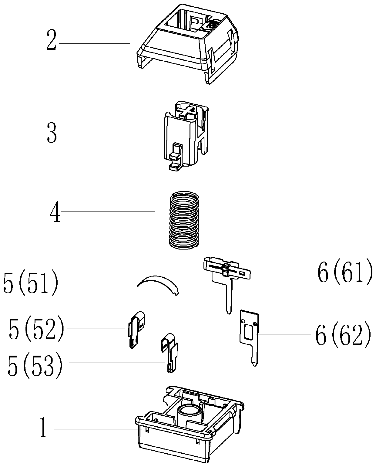
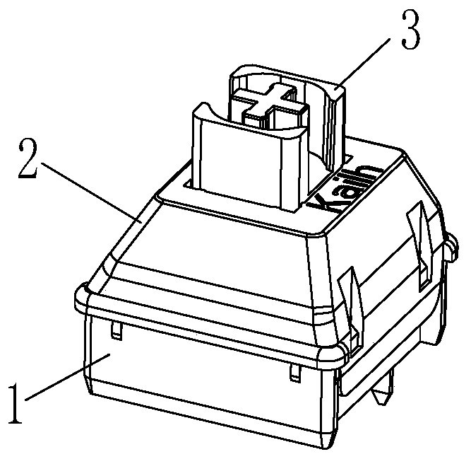
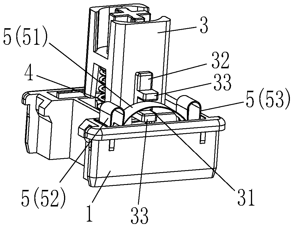
[0047] Please refer to Figure 1 to Figure 6 , the embodiment of the present invention provides a key switch with the function of pressing and sounding, which includes a base 1 and a cover 2 arranged above the base 1. The cover 2 is combined with the base 1 to form an accommodating cavity. A guide core 3 and an elastic member 4 located below the guide core 3 are respectively arranged in the accommodating chamber, and the elastic member 4 provides elastic restoring force for pressing the guide core 3 up and down; An opening through which the upper end of the guide core 3 passes. The key switch of this embodiment also includes an elastic sound-generating component 5 arranged in the accommodating cavity and on the side of the guide core 3, and a side notch 31 is formed on the side of the guide core 3, such as Figure 4 and Figure 5 shown; as Figure 4 and Figure 6 As shown, the elastic sounding component 5 includes an upper elastic piece 51 passing through the side notch 31...
Embodiment 2
[0077]The main difference between this embodiment and Embodiment 1 is that the conduction component of the key switch of this embodiment is different from that of Embodiment 1. The conduction component of this embodiment is a magnetic conduction component 7, such as Figure 20 to Figure 22 As shown, the magnetic conduction component 7 includes a magnet 71 disposed in the positioning post 35 and a magnetic inductor 72 disposed below the magnet 71, wherein a supply magnet 71 is provided on the lower end of the positioning post 35 upwards. An upper groove 351 is embedded, and a plurality of limiting blocks 352 located at the lower end of the magnet 71 protrude inward on the inner wall of the upper groove 351 . The magnet 71 is limited by the upper groove 351 , so that the magnet 71 moves up and down with the guide core 3 moving up and down.
[0078] In this embodiment, the magnetic inductor 72 can adopt various models. Preferably, a Hall element of the A3144EUAE model can be sele...
PUM
 Abstract
Description
Claims
Application Information
 - R&D
- Intellectual Property
- Life Sciences
- Materials
- Tech Scout
- Unparalleled Data Quality
- Higher Quality Content
- 60% Fewer Hallucinations
Browse by: Latest US Patents, China's latest patents, Technical Efficacy Thesaurus, Application Domain, Technology Topic, Popular Technical Reports.
© 2025 PatSnap. All rights reserved.Legal|Privacy policy|Modern Slavery Act Transparency Statement|Sitemap|About US| Contact US: help@patsnap.com


