
A Judgment Method and System for Simultaneous Commutation Failure of Multi-circuit DC

A DC system, commutation failure technology, applied in the direction of power transmission AC network, etc., can solve the problems of long time consumption, large amount of calculation, multi-circuit DC transmission power interruption, etc., to simplify the calculation and analysis process, easy to use, and shorten time consumption Effect

Active Publication Date: 2021-10-01
CHINA ELECTRIC POWER RES INST +2
View PDF2 Cites 0 Cited by
  • Summary
  • Abstract
  • Description
  • Claims
  • Application Information

AI Technical Summary

Problems solved by technology

In a multi-infeed DC transmission system, due to the close electrical coupling between DC inverter stations, a three-phase metallic short-circuit fault occurs on the commutation bus of one DC inverter side, which may lead to simultaneous commutation failure of multiple DC circuits. It will lead to the interruption of multiple DC transmission power, which brings great challenges to the safe and stable operation of the entire AC and DC system
At present, the conventional method for judging whether a three-phase metallic short-circuit fault on the commutation bus of a certain DC inverter side will cause simultaneous phase commutation failure of multiple DC systems is to use an electromechanical transient simulation program for fault scanning, which requires a large amount of calculation. time consuming

Method used


Image

  • A Judgment Method and System for Simultaneous Commutation Failure of Multi-circuit DC
  • A Judgment Method and System for Simultaneous Commutation Failure of Multi-circuit DC
  • A Judgment Method and System for Simultaneous Commutation Failure of Multi-circuit DC

Examples


Embodiment 1

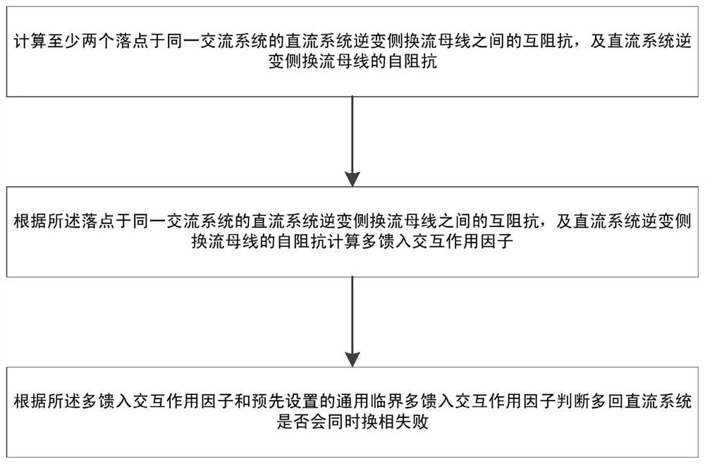
[0041] figure 1 A flow chart of a judging method for simultaneous commutation failure of multiple DC circuits provided by the present invention, as shown in figure 1 As shown, the present invention provides a method for judging the failure of multi-circuit DC simultaneous commutation, including:

[0042]Calculate the mutual impedance between at least two commutation buses on the inverter side of the DC system at the same AC system, and the self-impedance of the commutation buses on the inverter side of the DC system;

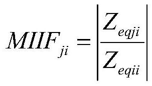
[0043] Calculate the multi-feed interaction factor according to the mutual impedance between the DC system inverter side commutation buses of the same AC system and the self-impedance of the DC system inverter side commutation buses;

[0044] According to the multi-infeed interaction factor and the preset universal critical multi-infeed interaction factor, it is judged whether the multi-circuit DC system will fail to commutate at the same time.

[0045] The mu...

Embodiment 2

[0059] Based on the same inventive concept, the present invention also provides a multi-circuit DC simultaneous commutation failure judging system, which may include:

[0060] The first calculation module is used to calculate the mutual impedance between at least two commutation buses on the inverter side of the DC system that fall on the same AC system, and the self-impedance of the commutation buses on the inverter side of the DC system;

[0061] The second calculation module is used to calculate the multi-feed interaction factor according to the mutual impedance between the DC system inverter side commutation buses of the same AC system and the self-impedance of the DC system inverter side commutation busbars ;

[0062] The judging module is used to judge whether the multi-circuit DC systems will fail to commutate at the same time according to the multi-infeed interaction factor and the preset universal critical multi-infeed interaction factor.

[0063] The second calculat...

Embodiment 3

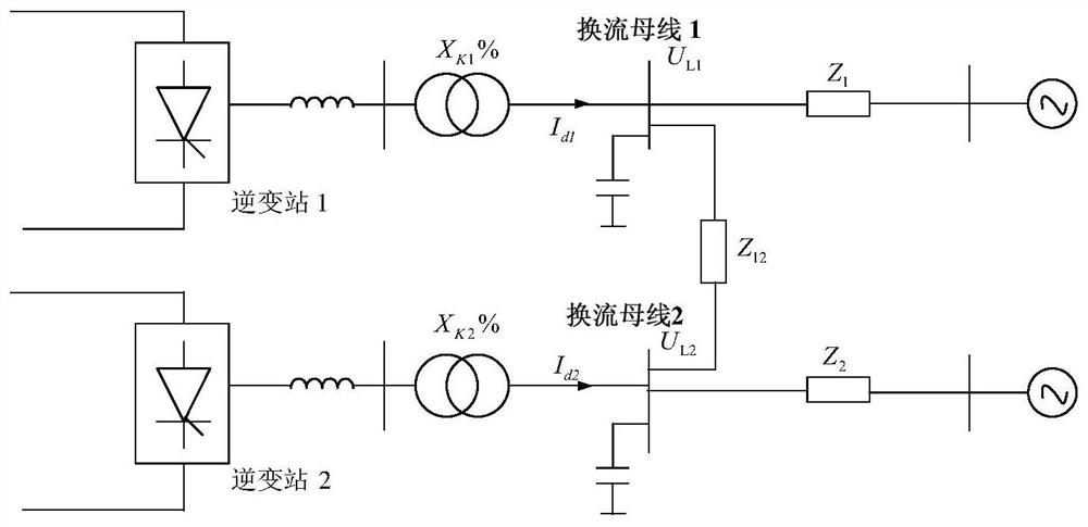
[0075] The present invention is further described in detail with a two-feed AC and DC example system, figure 2 It is a schematic diagram of the equivalent system of the two-feed AC and DC example system, such as figure 2 As shown in the example system, the commutation buses on the inverter side of the two-circuit DC system in the two-feed AC and DC system are connected by one AC line, and the AC system model at the receiving end is represented by the series equivalent impedance of the system equivalent potential source.

[0076] In the example system of the two feed-in AC and DC systems, the inverter side of the two-circuit DC system is connected to the adjacent same side, and the rectification side is independent from each other, and the sending end system is an infinite unit.

[0077] Using the multi-circuit DC simultaneous commutation failure judging method provided by the present invention to quickly judge whether a three-phase metallic short-circuit fault on the commuta...


PUM


Abstract

The present invention provides a judging method and system for simultaneous commutation failure of multi-circuit DC, including: calculating the mutual impedance between the commutation busbars on the inverter side of the DC system with at least two landing points on the same AC system, and the DC system inverter The self-impedance of the commutation bus on the transformer side; the multi-infeed is calculated according to the mutual impedance between the commutation buses on the inverter side of the DC transmission system in the same AC system, and the self-impedance of the commutation buses on the inverter side of the DC system Interaction factor: judging whether the multi-circuit DC system will fail to commutate at the same time according to the multi-infeed interaction factor and the preset universal critical multi-infeed interaction factor. The technical solution provided by the present invention can judge whether there will be multiple direct current commutation failures at the same time according to the given universal critical multi-feed interaction factor, which greatly simplifies the calculation and analysis process, shortens the time consumption, and is more convenient to use.

Description

technical field [0001] The invention belongs to the field of power system operation and planning, and in particular relates to a judging method and system for multi-circuit direct current simultaneous commutation failure. Background technique [0002] With the development of DC transmission technology, there has been a situation where multiple DC transmission systems are placed on the same AC system at close distances, that is, multi-infeed DC transmission systems. In a multi-infeed DC transmission system, due to the close electrical coupling between DC inverter stations, a three-phase metallic short-circuit fault occurs on the commutation bus of one DC inverter side, which may lead to simultaneous commutation failure of multiple DC circuits. It will lead to the interruption of multiple DC transmission power, which brings great challenges to the safe and stable operation of the entire AC and DC system. At present, the conventional method for judging whether a three-phase me...

Claims


Application Information

Patent Timeline
Patent Type & Authority Patents(China)
IPC IPC(8): H02J3/36
CPCH02J3/36Y02E60/60
Inventor 邵瑶汤涌周勤勇何剑
Owner CHINA ELECTRIC POWER RES INST
Learn More