Multi-size chip mounting device

A multi-size, chip technology, applied in the direction of electrical components, semiconductor/solid-state device manufacturing, circuits, etc., can solve the problems of not being able to adapt to complex situations, low work efficiency, and not being able to mount chips of different sizes at the same time, reaching the scope of application wide, improve work efficiency, and achieve the effect of installation

Active Publication Date: 2019-11-26
道晟半导体(苏州)有限公司
View PDF12 Cites 6 Cited by
  • Summary
  • Abstract
  • Description
  • Claims
  • Application Information

AI Technical Summary

Problems solved by technology

[0003] However, the existing placement equipment for multi-size chips on the market cannot mount chips of different sizes at the same time, and the work efficienc

Method used


Image

  • Multi-size chip mounting device
  • Multi-size chip mounting device
  • Multi-size chip mounting device

Examples


Embodiment 1

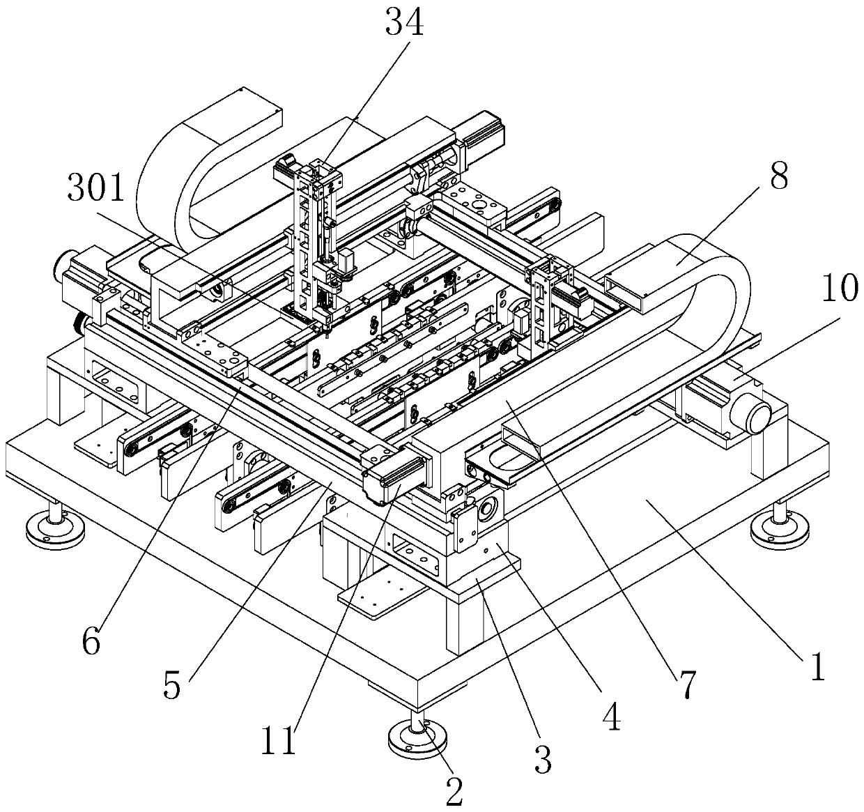
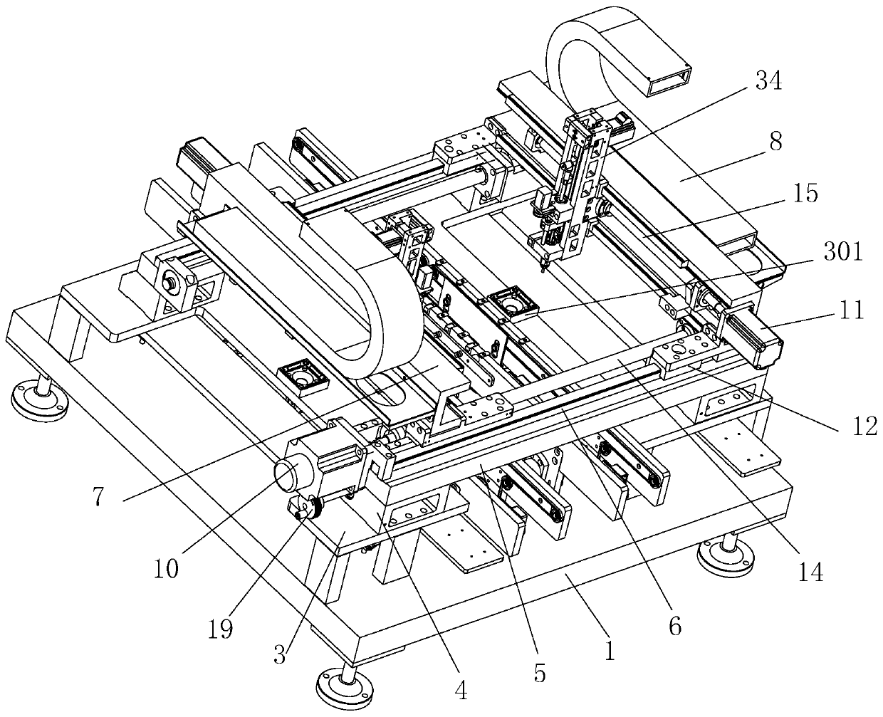
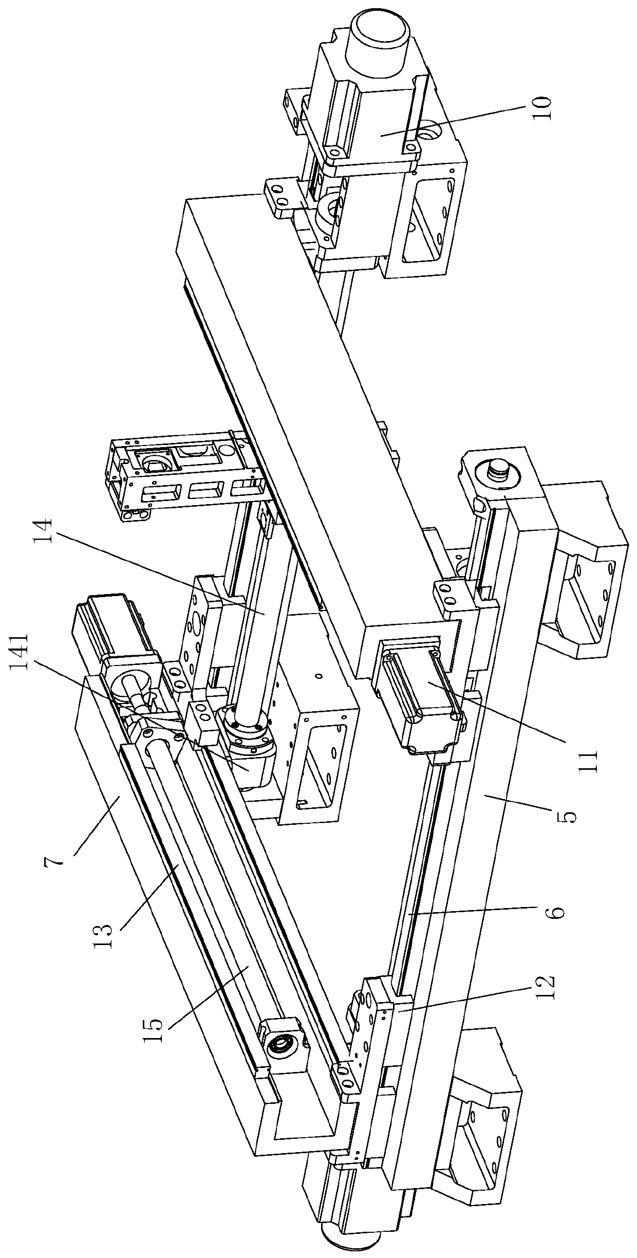
[0035] Embodiment 1: A mounting device for multi-size chips, including a support base 1, a support cross bar 5, a U-shaped fixing rod 7 and a mounting nozzle 39. The support base 1 is provided with two fixing seats 3, The fixing seat 3 is equipped with two supporting cross bars 5 perpendicular to the direction of the fixing seat 3, and one side of the supporting cross bar 5 is provided with a first screw rod 14, and one end of the first screw rod 14 is connected with The first motor 10, the first screw 14 is sleeved with a first screw sleeve 141 movable relative to the first screw 14, and each first screw sleeve 141 is connected with a first slider 12. The first sliding block 12 is slidably connected to the first sliding rail 6 above the supporting rail 5, and each first sliding rail 6 is provided with a first sliding block 12;

[0036] A U-shaped fixed rod 7 is slidably connected above the first slide rail 6, and the U-shaped fixed rod 7 is connected to the first sliding block 1...

Embodiment 2

[0043] Embodiment 2: A mounting device for multi-size chips, including a support base 1, a support cross bar 5, a U-shaped fixing rod 7 and a mounting nozzle 39. The support base 1 is provided with two fixing seats 3, The fixing seat 3 is equipped with two supporting cross bars 5 perpendicular to the direction of the fixing seat 3, and one side of the supporting cross bar 5 is provided with a first screw rod 14, and one end of the first screw rod 14 is connected with The first motor 10, the first screw 14 is sleeved with two first screw sleeves 141 that can move relative to the first screw 14, and each first screw sleeve 141 is connected with a first slide Block 12, the first sliding block 12 is slidably connected to the first sliding rail 6 above the support crossbar 5, and each first sliding rail 6 is provided with two first sliding blocks 12;

[0044] Two U-shaped fixed rods 7 are slidably connected above the first slide rail 6, and the U-shaped fixed rods 7 are connected to t...


PUM


Abstract

The invention provides a multi-size chip mounting device, comprising a supporting bottom plate, supporting cross bars, U-shaped fixing rods and mounting nozzles, wherein two fixing seats are arrangedon the supporting bottom plate, two supporting cross bars vertical to the fixing seat are installed on the fixing seat, a first lead screw is arranged on one side of the supporting cross bar, one endpart of the first lead screw is connected with a first motor, at least one first lead screw sleeve capable of moving relative to the first lead screw sleeves the first lead screw, a first slide blockis connected with each first lead screw sleeve, the first slide blocks are slidably connected to first slide rails above the supporting cross bars, and at least one first slide block is arranged on each first slide rail. The multi-size chip mounting device provided by the invention can realize the position change of front and rear, left and right, and up and down of the mounting nozzle, can also realize multi-angle rotation of the mounting nozzle in the circumferential direction, and can accurately locate the positions of the ships according to chips with different sizes, so that the mountingnozzle accurately suck the chips and place the chips at designated positions.

Description

Technical field [0001] The invention relates to a mounting device, in particular to a mounting device for multi-size chips. Background technique [0002] Chip mounter: also known as "mounter", "surface mount system" (Surface Mount System), in the production line, it is configured after the dispenser or screen printing machine, by moving the placement head to mount the surface A device that accurately places components on PCB pads. There is no need to drill insertion holes on the printed board, and the assembly technology of directly attaching and soldering surface assembly components to the specified position on the surface of the printed board is divided into manual and fully automatic. High assembly density, small size and light weight of electronic products. The volume and weight of SMD components are only about 1 / 10 of traditional plug-in components. Generally, after SMT is adopted, the volume of electronic products is reduced by 40%~60% and the weight is reduced by 60%~ 80...

Claims


Application Information

Patent Timeline
IPC IPC(8): H05K13/04
CPCH01L21/67144H01L21/6838H01L21/68H01L21/67742
Inventor 黄力蒋丽军
Owner 道晟半导体(苏州)有限公司
Why Eureka
Try Eureka