Transmission mechanism, sowing device and sowing method

A technology of transmission mechanism and driving mechanism, which is applied in the field of seeding device and transmission mechanism, which can solve the problems of sporadic planting, unstable adjustment of sowing or fertilization spacing, etc., and achieve the effect of saving material resources

Pending Publication Date: 2019-11-29
孙同梅
View PDF0 Cites 1 Cited by
  • Summary
  • Abstract
  • Description
  • Claims
  • Application Information

AI Technical Summary

Problems solved by technology

[0007] Aiming at the problem in the prior art that the spacing adjustment effect of sowing or fertilization is unstable and sporadic sowing is easy to occur, the present invention provides a transmission mechanism, a sowing device and a sowing method

Method used


Image

  • Transmission mechanism, sowing device and sowing method
  • Transmission mechanism, sowing device and sowing method
  • Transmission mechanism, sowing device and sowing method

Examples


Embodiment 1

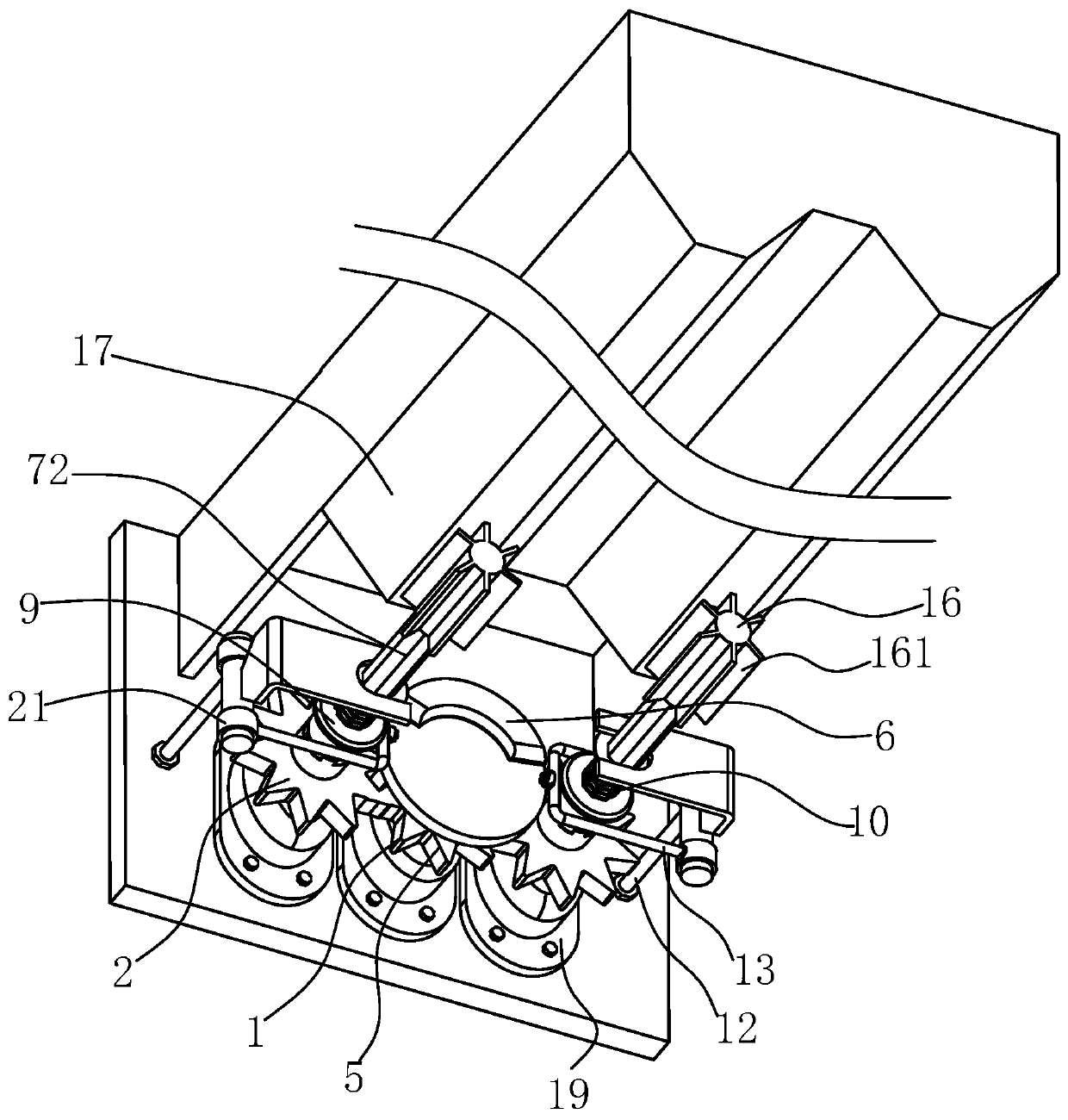
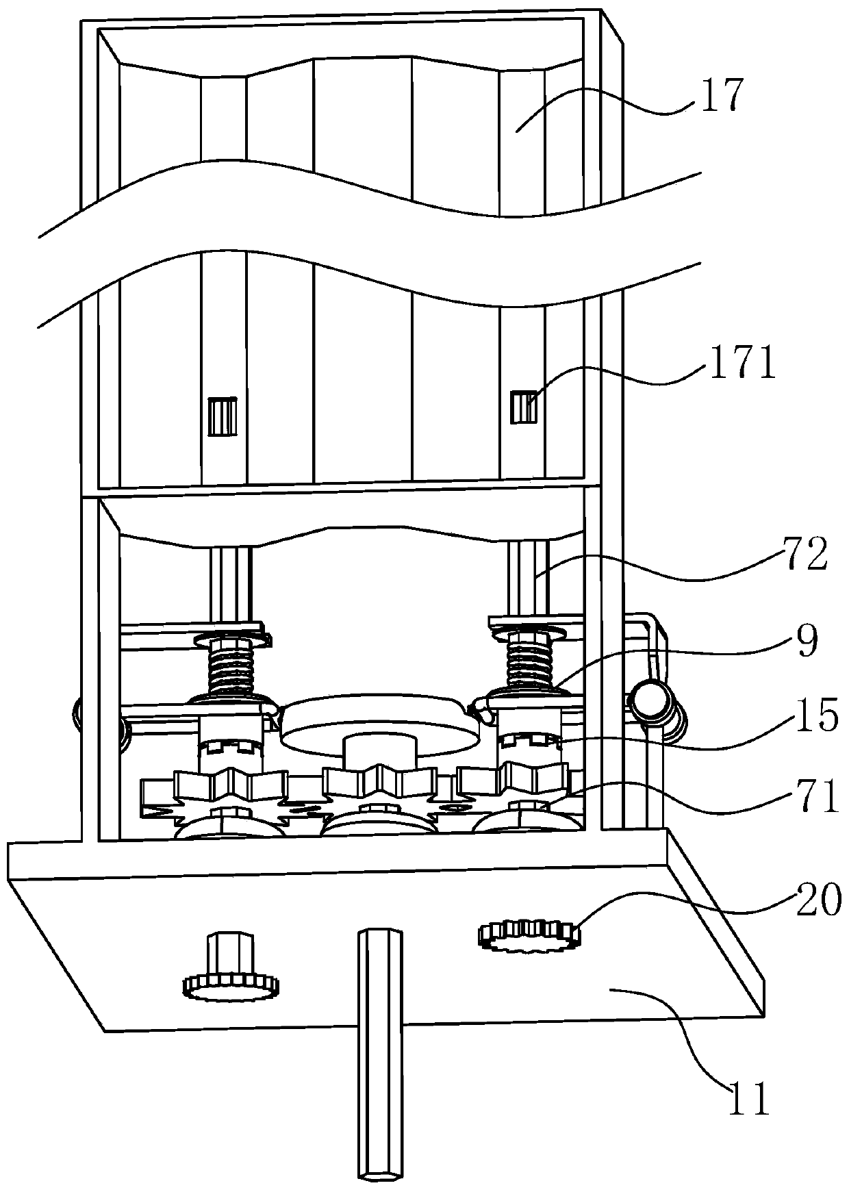
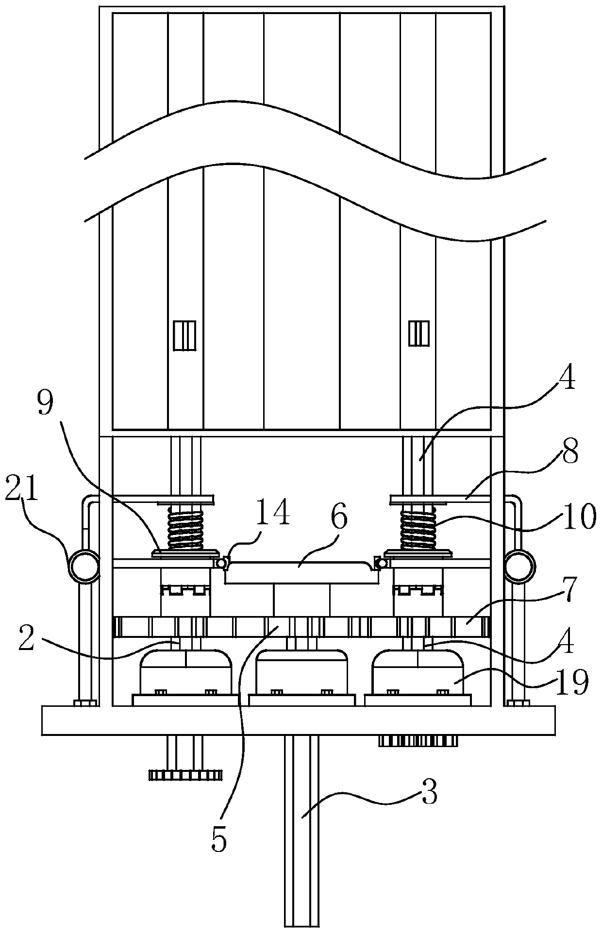
[0062] Such as Figure 1 to Figure 3 As shown, a transmission mechanism includes a base plate 11 and an intermittent driving mechanism, and the intermittent driving mechanism includes a driving part 1 and a driven part 2 driven by the driving part 1 . Specifically, the driving part 1 includes a driving shaft 3 , and the driven part 2 includes a driven shaft 4 . Two bearing seats 19 are installed on the base plate 11 , the driving shaft 3 and the driven shaft 4 respectively pass through the corresponding bearing seats 19 , and are both rollingly supported by the bearing seats 19 .

[0063] A driving wheel 5 is mounted on one end of the driving shaft 3, and a cam 6 is arranged on the driving wheel 5, and the end surface of the cam 6 is a cam, which can intermittently and smoothly push the driven part 2 to move. One side of the driving wheel 5 is fitted with a driven wheel 7 mounted on the driven shaft 4 , and in this embodiment, the driving wheel 5 is engaged with the driven wh...

Embodiment 2

[0082] On the basis that the basic technical solution of Embodiment 1 remains unchanged, there are two sets of driven parts 2 , which are respectively located on opposite sides of the active part 1 . When the driving wheel 1 rotates, the driving wheel 1 can alternately drive the driven parts 2 on both sides to act respectively, and finally realize the control of the feeding process of the two material boxes by the driven part.

[0083] The support member 12 is an L-shaped structure, which includes the support member in Embodiment 1 (as a part of the support member 12 in this embodiment) and the limiting plate (as the two parts of the support member 12 in this embodiment, and a The first part and the second part are perpendicular to each other), and the present implementation has hinged the push rod 13 on the support member 12. Specifically, for the control of the movable half shaft 72, the present embodiment further adopts the following technical solutions:

[0084] A support...

Embodiment 3

[0098] On the basis that the basic technical solution of Embodiment 1 remains unchanged, in this embodiment, a sprocket 20 is installed on the fixed half shaft 71, and another set of driven parts is arranged on the base plate 11, and the sprocket 20 is used as the driving drive. parts to drive another set of driven parts to move, and another set of newly added driven parts is used to cooperate with the installation of material boxes, so as to realize the joint fertilization or planting of multiple sets of material boxes. Specifically, in this embodiment, chemical fertilizers are placed in one set of material boxes, and bacterial fertilizers are placed in the other set of material boxes, so as to further spread the fertilizer evenly.

[0099] Of course, more driven parts and material boxes can also be set based on the above principles, including synchronous sowing of seeds with material boxes.


PUM


Abstract

The invention relates to a transmission mechanism, a sowing device and a sowing method, and belongs to the technical field of agricultural machine devices. The sowing device comprises an intermittentdriving mechanism. The intermittent driving mechanism comprises a driving part and a driven part driven by the driving part. The driving part comprises a driving shaft. The driven part comprises a driven shaft. One end of the driving shaft is provided with a driving wheel. A cam is arranged on the driving wheel. A driven wheel installed on the driven shaft is matched with one side of the driving wheel. The driven shaft is composed of a fixed half shaft and a movable half shaft which are independent of each other and have coinciding axes. The driven wheel is installed on the fixed half shaft. The movable half shaft is movably supported by a limiting plate. The movable half shaft can axially move relative to the limiting plate. A stop piece and a spring are arranged on the movable half shaft. One side face of the stop piece is attached to the cam. A push rod is driven by the cam to intermittently press the stop piece, the stop piece stops rotating, the movable half shaft is driven to rapidly stop, and seed material and fertilizers are precisely discharged and stop being discharged.

Description

technical field [0001] The invention relates to the technical field of agricultural machinery, in particular to a transmission mechanism, a sowing device and a sowing method. Background technique [0002] The function of the seeder is to evenly sow the seeds of the crops into the seed ditch of a certain depth with a certain amount of sowing or the distance between the plant and the hole, cover with an appropriate amount of fine wet soil, and properly suppress it, so as to provide good conditions for the germination of the seeds. To achieve high yield, stability, improve labor productivity of sowing operations, and reduce labor intensity of users. [0003] The existing seeder is mainly composed of main frame, walking wheels, ditching device, seeding device, transmission mechanism and soil suppression device, etc. When in use, it often sows or fertilizes continuously, resulting in the bulk density of sowing or fertilizing along the arrangement direction. Large, waste seeds, a...

Claims


Application Information

Patent Timeline
Patent Type & Authority Applications(China)
IPC IPC(8): A01C7/08A01C7/20A01C15/00A01C19/00F16H29/02
CPCA01C7/08A01C7/20A01C15/00A01C19/00F16H29/02
Inventor 孙同梅
Owner 孙同梅
Why Eureka
Try Eureka