Flushing unit for tool change mechanism of processing machine and quick tool change method

A technology of tool changing mechanism and processing machine, which is applied in the direction of metal processing machinery parts, metal processing equipment, manufacturing tools, etc. It can solve the problems of affecting the injection pressure, interfering with normal tool changing, polluting the tool magazine, etc., and achieves the effect of high efficiency and cleanliness

Active Publication Date: 2022-02-01
全准数控设备(苏州)有限公司
View PDF19 Cites 0 Cited by
  • Summary
  • Abstract
  • Description
  • Claims
  • Application Information

AI Technical Summary

Problems solved by technology

A larger one-way threshold will have certain resistance to the cutting fluid in the pipeline, which will affect the normal injection pressure. In addition, when the compressed air destroys the residual pressure, the general spindle has stopped, and the coolant will be sprayed to the spindle cutter. On the shank or tool, on the one hand, chips in the coolant may remain on the shank or tool, interfering with the normal tool change; on the other hand, the coolant remains on the shank or tool and continues to drip, especially when the spindle When the tool holder is replaced into the tool magazine, the residual coolant on it enters the tool magazine and continues dripping, polluting the tool magazine

Method used


Image

  • Flushing unit for tool change mechanism of processing machine and quick tool change method
  • Flushing unit for tool change mechanism of processing machine and quick tool change method

Examples


Embodiment 1

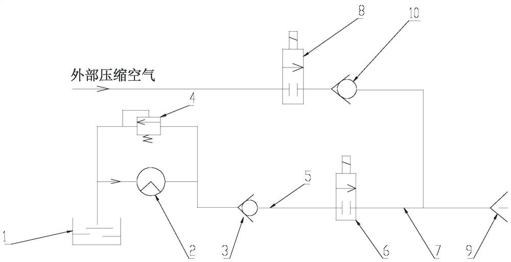
[0036]An embodiment of the present invention provides a flushing unit for a tool change mechanism of a processing machine, such as figure 1 As shown, it includes: a water pump 2, a first one-way valve 3, a second one-way valve 10, a first controllable valve 6, a second controllable valve 8 and a spray nozzle 9, wherein the first one-way valve 3 uses a paddle The one-way valve and the paddle-type one-way valve have strict restrictions on the installation method, and are suitable for vertical installation at the outlet of the water pump or horizontal installation under partial conditions. The first controllable valve 6 adopts an angle seat valve, and the second controllable valve 8 adopts a two-way electric control valve. In actual production applications, a liquid storage tank 1 is also required. The flushing liquid is stored in the liquid storage tank 1, and the flushing liquid can be As a cooling liquid during processing, it can also be used as a cleaning liquid for processin...

Embodiment 2

[0043] This embodiment provides a quick tool change method for a processing machine, which can be realized based on the flushing unit in the above-mentioned embodiment 1, and other key components in the processing machine can be known from the prior art, such as the processing spindle The drive and structure, the drive and structure of the tool magazine, so no more details.

[0044] The quick tool change method for a processing machine provided in this embodiment includes 4 key steps.

[0045] 1. Preparation steps for tool change.

[0046] In this step, the previous processing procedure has been completed and the cutter head needs to be replaced to process the workpiece in the next procedure. In the previous processing method, the processing spindle can be controlled to stop rotating, but in this step of the present invention, the processing spindle will still be controlled to continue to rotate after the processing is completed, but the control water pump is closed, the firs...


PUM


Abstract

The invention discloses a flushing unit and a quick tool-changing method for a tool-changing mechanism of a processing machine. The flushing unit includes: a water pump, a first one-way valve, a second one-way valve, a first controllable valve, a second controllable valve The control valve and spray nozzle, the water pump and the first controllable valve are closed at the same time, and the first check valve is automatically closed so that the flushing liquid in the pipeline between the first controllable valve and the first check valve is locked; the second controllable valve It is opened to allow external compressed air to pass through the second controllable valve and the second one-way valve to remove residues in the injection nozzle. Two parallel pipelines consisting of a controllable valve and a one-way valve are used to communicate with the spray nozzle, so that when the water pump stops working, the flushing fluid in the pipeline connected to it can be immediately locked to ensure that the machining spindle can be obtained immediately after cutting. The flushing liquid is infiltrated; the airflow sprays the residue in the spray nozzle so that the spray nozzle will not drip intermittently, and will not affect the locked flushing liquid in the pipeline connected to the water pump.

Description

technical field [0001] The invention relates to the technical field of numerical control machine tool processing, in particular to a flushing unit used for a tool change mechanism of a processing machine and a quick tool change method. Background technique [0002] Nowadays, multi-spindle machining has become a trend in the field of batch machining, but its automatic tool change technology is affected by the space structure, and there are still many problems at present, especially the layout of parallel machining spindles brings the impact of flushing fluid (that is, cutting fluid) during tool change. ) start and stop, processing spindle start and stop, processing spindle travel path and many other restrictions. [0003] From the perspective of machine tool users, it is hoped that the machine tool has the shortest auxiliary downtime as possible, especially the machining spindle needs to replace the tool head more frequently. The time required for the rotational speed (the p...

Claims


Application Information

Patent Timeline
Patent Type & Authority Patents(China)
IPC IPC(8): B23Q3/157B23Q11/00
CPCB23Q3/157B23Q11/005
Inventor 赵淑媛
Owner 全准数控设备(苏州)有限公司
Why Eureka
Try Eureka