Pose identifying and grabbing device and method based on binocular vision

A binocular vision, pose technology, applied in manipulators, program-controlled manipulators, manufacturing tools, etc., can solve the problem of not considering the initial and final attitude of the product, and achieve the effect of improving efficiency

Pending Publication Date: 2019-11-29
CHINA JILIANG UNIV
View PDF0 Cites 40 Cited by
  • Summary
  • Abstract
  • Description
  • Claims
  • Application Information

AI Technical Summary

Benefits of technology

This technology helps identify if there are no objects being processed by an industrial robot arm or other machine tool without loading them onto it for better performance. It uses two different systems - one captures images from the surface while another analyzes these captured images to determine its poses accurately. These results help robots make informed decisions about how best they handle their tasks based upon this knowledge provided through motion analysis techniques such as stereo cameras.

Problems solved by technology

The technical problem addressed in this patents relates to improving the accuracy and precision of robotic arm movements during manufacturing processes due to factors like uneven surfaces or shock loading caused when handling fragile items with heavy loads. This requires precise knowledge about how well these tools are designed and controlled properly.

Method used


Image

  • Pose identifying and grabbing device and method based on binocular vision
  • Pose identifying and grabbing device and method based on binocular vision
  • Pose identifying and grabbing device and method based on binocular vision

Examples


specific Embodiment approach

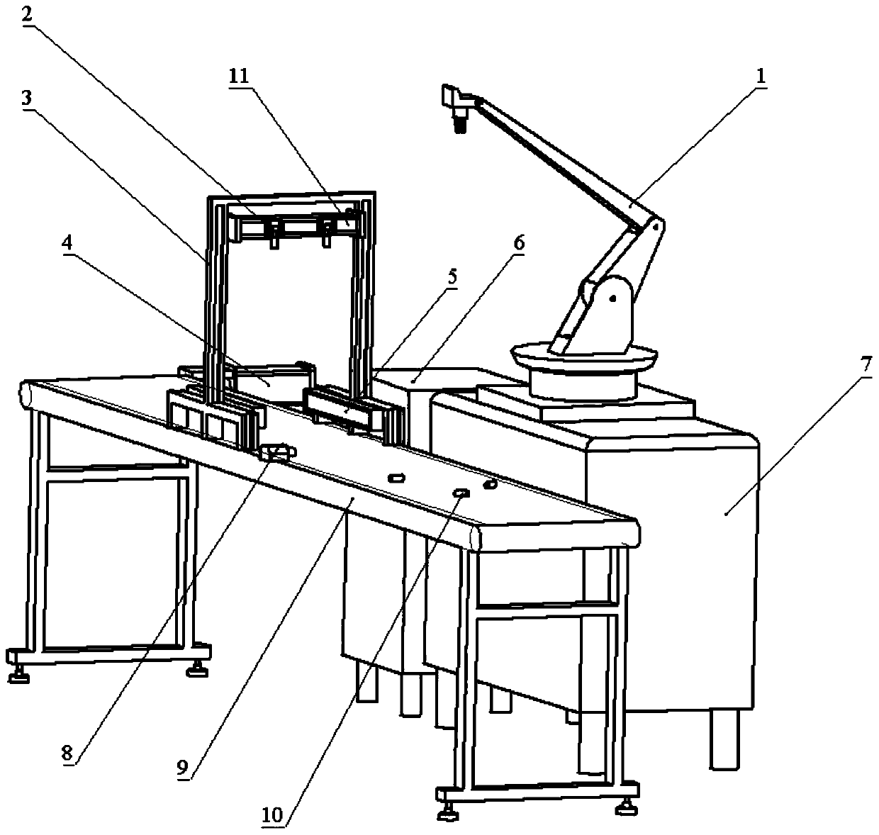
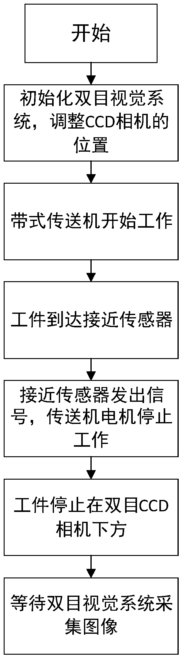
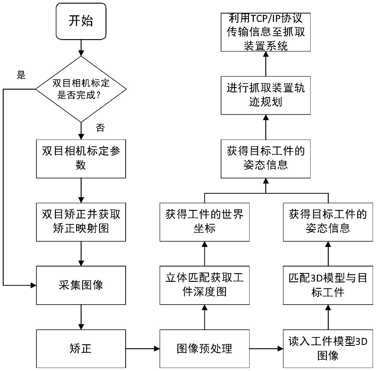
[0055] Specific implementation methods (such as image 3 and Figure 4 shown):

[0056] Such as Figure 5 The gray coordinate system (X, Y, Z) shown is the camera coordinate system, and the two black two-dimensional coordinate systems are the pixel coordinate system (x, y) of the left and right cameras respectively. The pixel coordinate system of the left camera is located at At (0,0,0) of the camera coordinate system, the pixel coordinate system of the right camera is located at (Tx,0,0) of the camera coordinate system. (X, Y, Z) in the figure is a point in the camera coordinate system.

[0057] Such as Figure 6 Shown is the workpiece coordinate system, which is established based on the center of the bottom circle of the target workpiece.

[0058] Such as Figure 7 Shown is the coordinate system of the manipulator, established with the origin of the center of the manipulator base.

[0059] Step 1: by adjusting the height of the industrial camera 2, the shooting angle ...


PUM


Abstract

The invention discloses a pose identifying and grabbing device and method based on binocular vision. The device comprises a workpiece conveying module, an image collecting module and a target workpiece grabbing module. The workpiece conveying module is used for conveying a target workpiece to the position below a binocular camera through a conveying belt, when a proximity sensor installed below abinocular vision camera support receives an arrival signal of the workpiece, the conveying belt stops working, and a left industrial camera and a right industrial camera can collect images conveniently. The image collecting module collects the images and then transmits the images to a computer, pose information of the target workpiece is obtained after an image preprocessing algorithm and a pose identifying algorithm are used for processing, then the pose information is processed, track planning is conducted, and data are transmitted to the grabbing device; and a mechanical hand in the grabbing device is used for grabbing the workpiece and placing the workpiece to a designated area. By means of the pose identifying and grabbing device and method based on binocular vision, the pose information of the target workpiece can be detected, track planning is conducted, the grabbing device is used for grabbing the target workpiece, and efficiency is improved.

Description


Claims


Application Information

Patent Timeline
Owner CHINA JILIANG UNIV
Why Eureka
Try Eureka