A multi-stage rate regulation method for steam turbine feed-forward

A speed regulation and steam turbine technology, applied in steam engine devices, mechanical equipment, engine components, etc., can solve the problems that the automatic gain control adjustment performance cannot meet the needs, etc., and achieve the effects of reducing overshoot, stable steam pressure, and increasing adjustment speed

Active Publication Date: 2021-12-24
黑龙江苑博信息技术有限公司 +3
View PDF0 Cites 0 Cited by
  • Summary
  • Abstract
  • Description
  • Claims
  • Application Information

AI Technical Summary

Problems solved by technology

[0006] The purpose of the present invention is to solve the problem that the existing automatic gain control adjustment performance on the steam turbine side cannot meet the needs when the load varies in a large range, and provides a multi-stage rate adjustment method for steam turbine feed-forward

Method used


Image

  • A multi-stage rate regulation method for steam turbine feed-forward
  • A multi-stage rate regulation method for steam turbine feed-forward
  • A multi-stage rate regulation method for steam turbine feed-forward

Examples


specific Embodiment approach 1

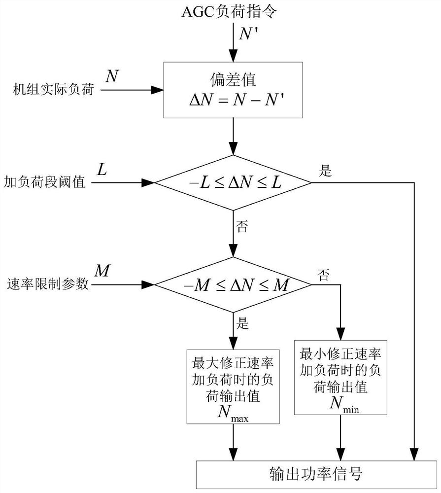
[0031] Specific implementation mode one: the following combination figure 1 Describe this embodiment, the multi-stage rate adjustment method of steam turbine feed-forward described in this embodiment, the specific process of this adjustment method is:

[0032] S1. Obtain the AGC load command N' and the actual load N of the unit, and calculate the deviation value ΔN=N-N';

[0033] S2. Acquiring the loading segment threshold L;

[0034] S3. Determine the range of the deviation value ΔN. If it is -L≤ΔN≤L, the output power signal is the actual load N of the unit. If not, execute S4;

[0035] S4. Calculate the rate limit parameter M in real time;

[0036] S5. Judging the range of the deviation value ΔN, if it is -M≤ΔN≤M, then add the load output value N when the maximum correction rate is applied to the load max As the output power signal, otherwise the load output value N when the minimum correction rate is added to the load min as the output power signal.

[0037] In this em...

specific Embodiment approach 2

[0040] Specific implementation mode 2: This implementation mode further explains the implementation mode 1. The specific method for obtaining the loading segment threshold L described in S2 is:

[0041] L=1%×(35%~40%)×N 0 ;

[0042] Among them, N 0 Indicates the rated load of the unit.

[0043] In this embodiment, for the selection of the threshold value L of the load segment, the maximum deviation value of the unit during the adjustment process cannot exceed 1% of the rated load of the unit. Therefore, the threshold L of the load segment is based on 1% of the rated load of the unit. % to 40% (about 1 / 3) is used as the basis for judging whether to correct the power signal to the main controller of the steam turbine.

specific Embodiment approach 3

[0044] Specific implementation mode 3: This implementation mode further explains the implementation mode 1 or 2. The specific method for calculating the rate limit parameter M in real time as described in S4 is as follows:

[0045] M=d(C b (P dt -P d0 )) / dt;

[0046] Among them, P dt Indicates the minimum pressure of the unit, P d0 Indicates the load point pressure, C b Indicates the energy storage coefficient of the boiler.

[0047] In this embodiment, P dt Indicates the minimum pressure of the unit. When adding or subtracting load, take the 300MW unit as the benchmark, P dt Under the premise of avoiding the trigger lock increase and decrease of 0.6Mpa, the upper and lower fluctuations are ±0.1Mpa, and the minimum deviation is set to 0.5Mpa.


PUM


Abstract

The multi-stage speed adjustment method of steam turbine feed-forward belongs to the technical field of electric power system automatic control. The invention aims to solve the problem that the existing automatic gain control adjustment performance of the steam turbine side cannot meet the needs when the load changes in a large range. The specific process of the adjustment method of the present invention is: obtain the AGC load instruction and the actual load of the unit, calculate the deviation value ΔN; obtain the threshold value L of the loading section; judge the range of the deviation value ΔN, if -L≤ΔN≤L, the output power signal is the unit Actual load; otherwise, calculate the rate limit parameter M in real time; judge the range of the deviation value ΔN, if -M≤ΔN≤M, then use the load output value when the maximum correction rate is added to the load as the output power signal, otherwise, add the minimum correction rate to the load When the load output value is used as the output power signal. The invention is used in thermal power units.

Description

technical field [0001] The invention relates to a feed-forward multi-stage rate adjustment method of a steam turbine, which belongs to the technical field of electric power system automatic control. Background technique [0002] In recent years, the proportion of new energy represented by solar energy and wind energy in the power generation system has increased year by year. New energy sources such as solar energy and wind energy have strong randomness, which brings new challenges to the stability of the power grid and also poses a challenge to the traditional The load response capability of thermal power units puts forward higher requirements. [0003] In this context, it is imperative to improve the regulation performance of the AGC (Automatic Gain Control) on the power generation side. The traditional AGC regulation system uses the unit CCS (Coordination System) as the main executor, which receives the AGC signal from the power grid, and after signal processing , to coor...

Claims


Application Information

Patent Timeline
Patent Type & Authority Patents(China)
IPC IPC(8): F01D17/10F01K11/02F01K13/02
CPCF01D17/10F01K11/02F01K13/02
Inventor 石家魁姚坤万杰曹勇任国瑞付俊丰孙殿承张磊江万泽李晓明刘东旭
Owner 黑龙江苑博信息技术有限公司
Why Eureka
Try Eureka