A rapid detection system for fiber breakage in fiber optic fences
A detection system and optical fiber technology, which is applied in transmission systems, optical instrument testing, electromagnetic wave transmission systems, etc., can solve the problems of false detection and alarm delay of fiber breakage detection in optical fiber fences, and achieve the effect of less increase and less cost.
- Summary
- Abstract
- Description
- Claims
- Application Information
AI Technical Summary
Problems solved by technology
Method used
Image

Examples
Embodiment Construction
[0023] The present invention will be described in further detail below in conjunction with the accompanying drawings.
[0024] This specific embodiment is only an explanation of the present invention, and it is not a limitation of the present invention. Those skilled in the art can make modifications to this embodiment without creative contribution as required after reading this description, but as long as they are within the protection of the present invention are protected by patent law.
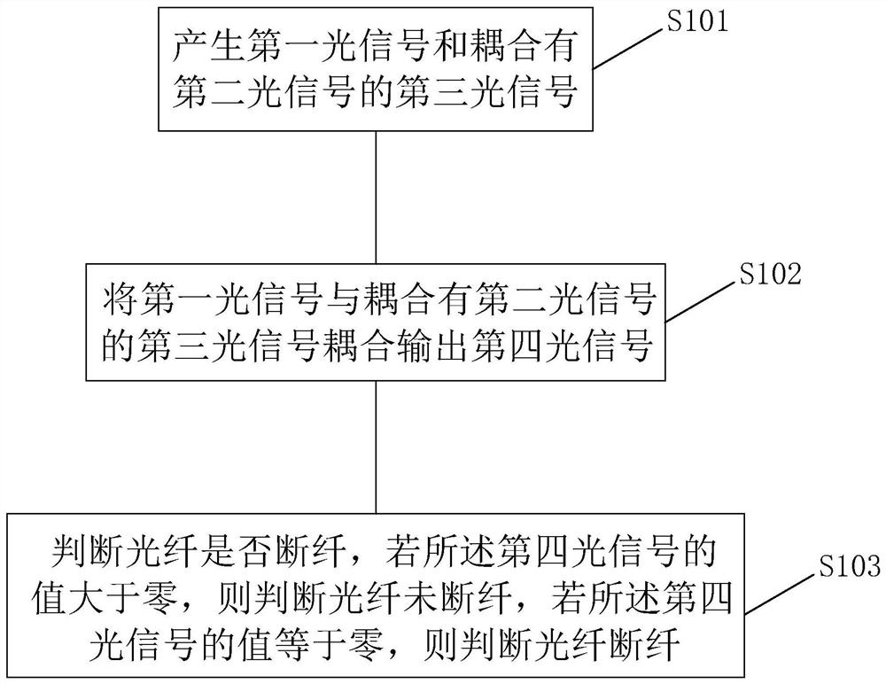
[0025] image 3 It is a flow chart of a method for quickly detecting fiber breakage in an optical fiber fence according to an embodiment of the present invention. The method includes steps:
[0026] S101: Generate a first optical signal and a third optical signal coupled with the second optical signal;
[0027] Specifically, such as Figure 4 The shown flow chart of generating a first optical signal and a third optical signal coupled with a second optical signal includes steps:
[0028...
PUM
 Abstract
Description
Claims
Application Information
 - Generate Ideas
- Intellectual Property
- Life Sciences
- Materials
- Tech Scout
- Unparalleled Data Quality
- Higher Quality Content
- 60% Fewer Hallucinations
Browse by: Latest US Patents, China's latest patents, Technical Efficacy Thesaurus, Application Domain, Technology Topic, Popular Technical Reports.
© 2025 PatSnap. All rights reserved.Legal|Privacy policy|Modern Slavery Act Transparency Statement|Sitemap|About US| Contact US: help@patsnap.com