
Optical measurement device with light beam control function

An optical measurement and beam control technology, which is applied in measurement devices, phase influence characteristic measurement, and material analysis by optical means. Effect

Inactive Publication Date: 2019-11-29
CHANGCHUN INST OF OPTICS FINE MECHANICS & PHYSICS CHINESE ACAD OF SCI
View PDF8 Cites 3 Cited by
  • Summary
  • Abstract
  • Description
  • Claims
  • Application Information

AI Technical Summary

Problems solved by technology

[0004] In view of this, in order to solve the technical problems of high cost, complex structure and large measurement error in the multi-band optical nonlinear measurement device in the prior art, the present invention further expands the range of the measurement spectrum and provides an optical measurement device with beam control function

Method used


Image

  • Optical measurement device with light beam control function
  • Optical measurement device with light beam control function
  • Optical measurement device with light beam control function

Examples


Embodiment Construction

[0032] In order to enable those skilled in the art to better understand the technical solution of the present invention, the present invention will be further described in detail with the accompanying drawings below. However, it should be understood that these descriptions are only for further illustrating the features and advantages of the present invention, rather than limiting the claims of the present invention.

[0033]The terms used in the present invention generally have the meanings commonly understood by those skilled in the art, unless otherwise specified.

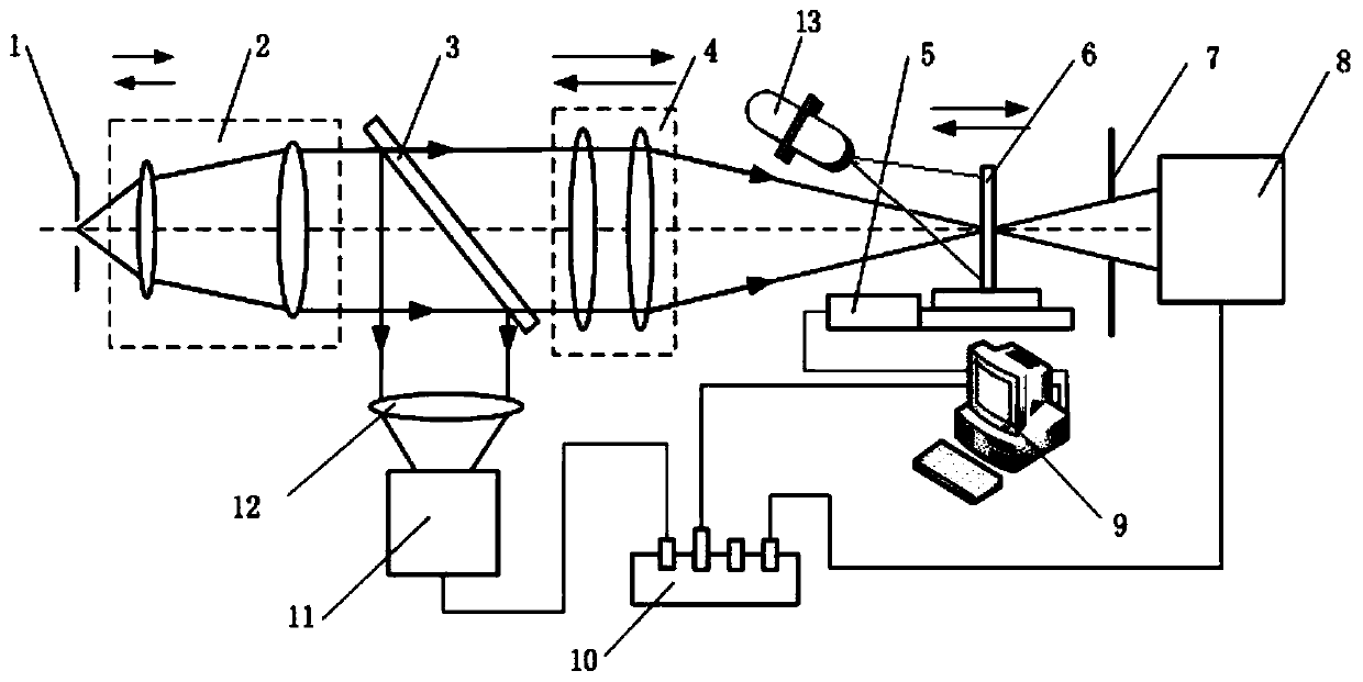
[0034] Such as Figure 1-3 As shown, the optical measurement device with beam control function of the present invention includes a laser collimation system 2, a beam splitter 3, a focusing optical system 4, an electric displacement platform 5, an aperture plate 7, a first power meter 8, a main control Computer 9, data acquisition instrument 10, second power meter 11 and first lens 12.

[0035] Wherein, the lase...


PUM


Abstract

The invention relates to an optical measurement device with a light beam control function, belongs to the technical field of optical non-linear measurement devices, solves technical problems of high cost, complex structure, large measurement error and the like of a multi-band optical non-linear measurement device in the prior art and further enlarges the measurement spectrum range. The optical nonlinear measurement device comprises a laser collimation system, a beam splitter, a focusing optical system, an electric displacement platform, a diaphragm, a first power meter, a main control computer, a data acquisition instrument, a second power meter and a first lens. The optical non-linear measuring device can measure a non-linear absorption coefficient and a non-linear refraction coefficientof a material in real time, is wide in measurement wavelength spectrum band, simple in principle, high in measurement precision and low in cost, and has a function of measuring the film system damagethreshold of an optical element.

Description

technical field [0001] The invention belongs to the technical field of optical measuring devices, and in particular relates to an optical measuring device with a light beam control function. Background technique [0002] Nonlinear optical materials have important applications in the fields of laser protection and optical limiting. The research on the nonlinear characteristics of materials is currently a research hotspot in materials science and related fields. In the existing technology, optical nonlinear measurement techniques include degenerate four-wave mixing, three-wave mixing, third harmonic method, nonlinear interferometry, non-linear Linear ellipsometry, Mach-Zehnder interference method, 4f phase coherent imaging method, Z-scan method, etc. Among them, Z-scan method (M.Sheik-Bahae, A.A.Said, Tai-Hui Wei, DavidJ.Hagan, E.W.Van Stryland .Sensitive, measurement of optical nonlinearities using a single beam.IEEE J QuantumElect, 26,760-769(1990)) is relatively common. Du...

Claims


Application Information

Patent Timeline
IPC IPC(8): G01N21/17G01N21/41
CPCG01N21/17G01N21/41
Inventor 汤伟邵俊峰王挺峰刘立生刘志超
Owner CHANGCHUN INST OF OPTICS FINE MECHANICS & PHYSICS CHINESE ACAD OF SCI
Learn More