Eureka AIR delivers breakthrough ideas for toughest innovation challenges, trusted by R&D personnel around the world.

Vacuum chamber high-voltage power supply leading-in device

A high-voltage power supply and introduction device technology, applied in electrical components, accelerators, etc., can solve the problems of difficult to shield electric field and high-voltage discharge, unable to shield discharge, affecting the normal operation of electron accelerators, etc., to ensure normal operation and avoid high-voltage discharge. Effect

Pending Publication Date: 2019-11-29
无锡爱邦辐射技术有限公司
View PDF0 Cites 0 Cited by
  • Summary
  • Abstract
  • Description
  • Claims
  • Application Information

AI Technical Summary

Problems solved by technology

And because there is no shielding measure between the high-voltage bushing and the first insulating flange, it is difficult to shield and evenly distort the electric field and high-voltage discharge between the high-voltage bushing and the first insulating flange
In addition, since the inner ends of the two electrodes 4 respectively pass through the two through holes on the second insulating flange and protrude from the inner side of the second insulating flange, the inner ends of the two electrodes 4 have no shielding measures and cannot be shielded. Discharge phenomenon occurs due to electric field distortion caused by uniform irregular shape and metal part tip
In summary, all the above problems will affect the normal operation of the electron accelerator

Method used


Image

  • Vacuum chamber high-voltage power supply leading-in device

Examples


Embodiment Construction

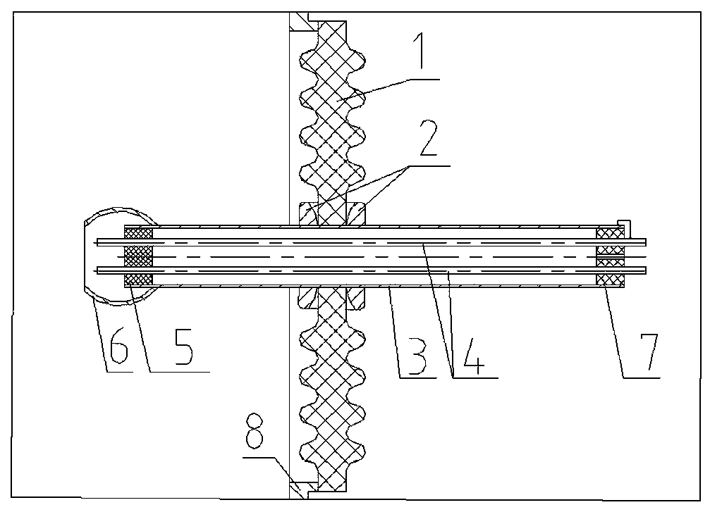
[0014] like figure 1 As shown, the vacuum chamber high-voltage power supply introduction device of the present invention includes a vacuum chamber, and a mounting hole is processed on the wall 8 of the vacuum chamber, and a first insulating flange 1 is installed in the mounting hole. The first insulating flange is a flange plate made of No. 95 ceramics, the center of which is flat on both sides and equipped with rubber sealing rings for isolating vacuum and gas. A high voltage bushing 3 is installed inside the first insulating flange 1 . The high-voltage bushing 3 is made of No. 304 stainless steel, and its two ends extend into the vacuum chamber and the outside of the vacuum chamber respectively. The high-voltage bushing 3 on both sides of the first insulating flange 1 is covered with shielding rings 2. The shielding Ring 2 is a metal ring supported by No. 304 stainless steel with an arc-shaped side. The arc-shaped surfaces of the two shielding rings face the plane at the ce...


PUM


Abstract

The invention relates to a vacuum chamber high-voltage power supply leading-in device. The device comprises a vacuum chamber, and a mounting hole is formed in the wall of the vacuum chamber; a first insulating flange is arranged in the mounting hole, and a high-voltage bushing is arranged in the first insulating flange. The two ends of a high-voltage bushing extend out of the vacuum chamber and the vacuum chamber respectively, and a second insulating flange and a positioning flange are arranged in the two ends of the high-voltage bushing respectively. The second insulating flange and the positioning flange are respectively provided with two through holes, and two electrodes are arranged in the high-voltage bushing. The inner ends of the two electrodes respectively penetrate through two through holes in the second insulating flange and then extend out of the inner side of the second insulating flange. The device is characterized in that the two surfaces of the first insulating flange are wavy, and shielding rings are sleeved on the high-voltage bushing on the two sides of the first insulating flange respectively, and the outer ends of the two electrodes penetrate through two throughholes in the positioning flange respectively and then extend out of the positioning flange. By adopting the device, the influence on the electron accelerator can be avoided, and the normal work of the electron accelerator can be ensured. The device is suitable for high-voltage power supply introduction of vacuum chambers.

Description

technical field [0001] The invention relates to a high-voltage power supply. Specifically, it is a power introduction mechanism that introduces high-voltage power into the vacuum chamber. High-voltage power supply suitable for the vacuum chamber where the electron accelerator filament is located. Background technique [0002] It is well known in the electron accelerator production industry that the electron accelerator filament is installed in a vacuum chamber, and the power required for its work is a high-voltage power supply and must be introduced from the outside. The introduction mechanism of high-voltage power supply is an important part of the electron accelerator's electric vacuum system. Whether it can withstand high vacuum, high pressure and high voltage is an important condition for the normal and stable operation of the electron accelerator. [0003] The traditional vacuum chamber high-voltage power supply introduction device is processed with a mounting hole on...

Claims


Application Information

Patent Timeline
Patent Type & Authority Applications(China)
IPC IPC(8): H05H7/14
CPCH05H7/14
Inventor 张宇蔚陈龙飞
Owner 无锡爱邦辐射技术有限公司
Why Eureka
Eureka Blog
Learn More