Blind-mating grounding clamping piece structure of electrical cabinet box

A grounding clip and sheet structure technology, applied in the printed circuit grounding device, electrical equipment shell/cabinet/drawer, electrical components, etc., can solve the problems of overall rigidity reduction, inability to loosen socket pin, socket pin shaking, etc. The effect of reducing the number of parts, reducing the cost of the chassis, and facilitating the production and installation

Pending Publication Date: 2019-11-29
置恒卓能电气科技(滁州)有限公司 +1
View PDF0 Cites 2 Cited by
  • Summary
  • Abstract
  • Description
  • Claims
  • Application Information

AI Technical Summary

Problems solved by technology

However, the plastic chassis shell itself is not suitable for threaded structure and there is not enough glue thickness for the threaded structure. If it is made into a split type, the overall rigidity of the plastic chassis shell will be greatly reduced, which makes it impossible for the plug and socket components to be mated in advance. Well, when installing, you can only install the plug first, and then install the socket assembly to match the plug. During this process, because the socket assembly is inside the plastic case, and the plastic case is deep and narrow, the socket cannot be seen The process of component insertion
[0005] In practice, it is found that the plastic chassis shell scheme has the following deficiencies: 1. The grounding wire interface post of the chassis and the socket female pin have high requirements for coaxiality during mating. During the blind insertion process of the socket assembly, due to the existence of the installation gap, It is difficult to ensure that it can be aligned and mated; 2. The socket female pin is screwed on the threaded hole of the grounding guide plate. Due to the limitation of the structural space, the socket female pin cannot be given a relaxed structure, so in the process of blind insertion In the middle, the female pin of the socket will inevitably shake a little, which is tantamount to increasing the difficulty of alignment and mating again.

Method used


Image

  • Blind-mating grounding clamping piece structure of electrical cabinet box
  • Blind-mating grounding clamping piece structure of electrical cabinet box
  • Blind-mating grounding clamping piece structure of electrical cabinet box

Examples


Embodiment Construction

[0038] The specific embodiments of the present invention will be described in detail below in conjunction with the accompanying drawings, so that those skilled in the art can more clearly understand how to practice the present invention. While the invention has been described in connection with preferred specific embodiments thereof, these embodiments are illustrative only and are not intended to limit the scope of the invention.

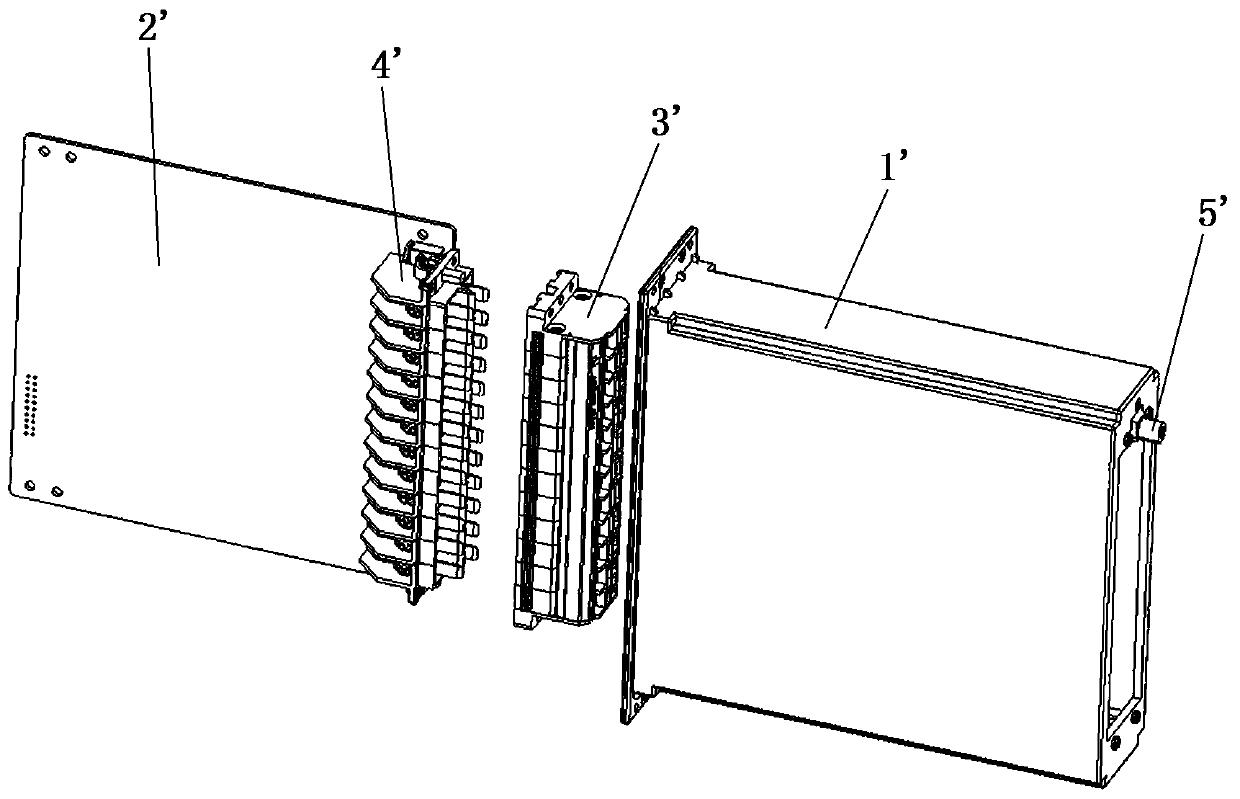
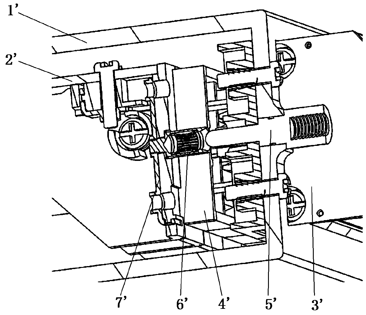
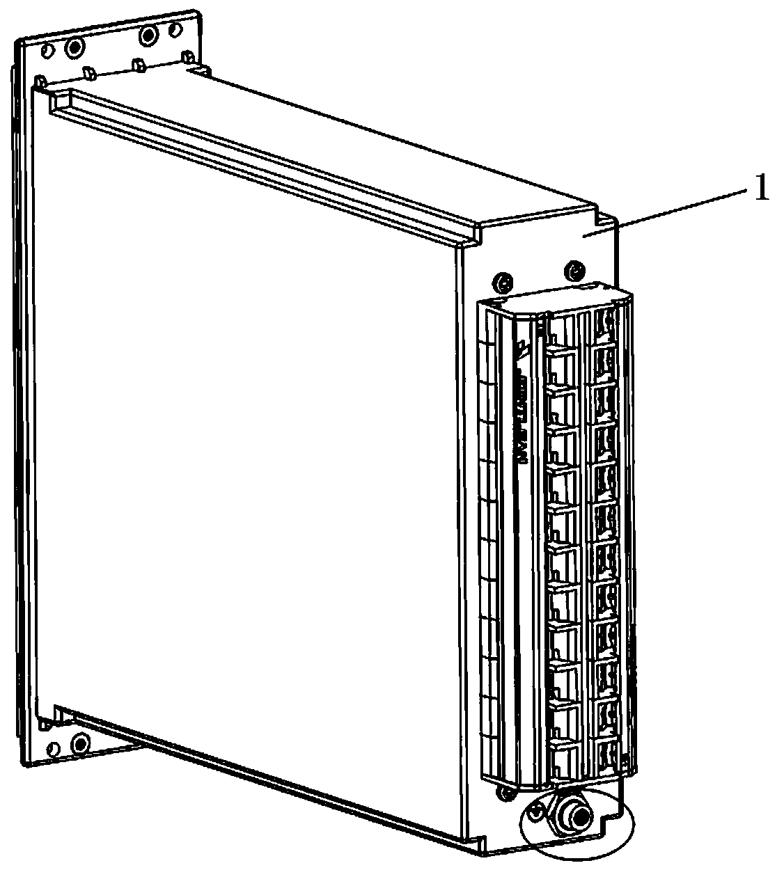
[0039] see image 3 with Figure 4 , a blind-mating grounding clip structure of an electrical cabinet chassis, comprising a plastic chassis shell 1, a PCB board 2, a chassis grounding wire interface post 3, a grounding conductive clip 4, an elastic booster reed 5, and a fastening nut 6.

[0040] The PCB board 2 is mounted on the inner side of the plastic case shell 1 , and the PCB board 2 is provided with a PCB board grounding electrode 201 .

[0041] The plastic case shell 1 is provided with a through hole, and the case ground wire interface post...


PUM


Abstract

The utility model discloses a blind-mating grounding clamping piece structure of an electrical cabinet box. The structure comprises a plastic cabinet shell, a PCB, a cabinet grounding wire interface column, a grounding conductive clamping piece, an elastic power-assisted reed and a fastening nut; the PCB is mounted on the inner side of the plastic cabinet shell; a PCB grounding electrode is arranged on the PCB; the cabinet grounding wire interface column is mounted in a through hole formed in the plastic cabinet shell; one end of the grounding conductive clamping piece and one end of the elastic power-assisted reed are connected with one end, in the plastic cabinet shell, of the cabinet grounding wire interface column. The other end of the grounding conductive clamping piece is in contactconnection with the PCB grounding electrode, the elastic power-assisted reed is attached to the grounding conductive clamping piece, and the fastening nut is arranged on the outer side of the plasticcabinet shell and is in threaded connection with the cabinet grounding wire interface column. By adopting the plastic cabinet shell, the cost, the weight and the production period of a cabinet are reduced, the cabinet grounding wire interface column is connected with the grounding conductive clamping piece and the elastic power-assisted reed to form the grounding assembly, the number of parts is reduced, the production and installation are facilitated, and the assembly efficiency is improved.

Description

technical field [0001] The invention relates to the technical field of electrical cabinets, in particular to a blind-mating ground clip structure of the electrical cabinet. Background technique [0002] Nowadays, most of the chassis shells in domestic electrical control cabinets are made of high-quality aluminum alloy profiles or galvanized steel plates. The metal chassis shell generally includes the main shell of the chassis and the rear panel. When installing the terminal block, first lock the plug on the rear panel, and the socket assembly is inserted with the PCB board and the plug, and then the plug and socket assembly are fastened with fastening screws. Lock it tightly, then insert it into the main casing of the chassis as a whole, and finally use the fixing screws to lock the rear panel to the main casing of the chassis. In this way, the grounding current on the PCB board is connected to the grounding guide plate through the screws of the PCB board, and then connecte...

Claims


Application Information

Patent Timeline
Patent Type & Authority Applications(China)
IPC IPC(8): H05K5/02H05K1/02H01R4/66H01R13/15H01R12/71
CPCH01R4/66H01R12/716H01R13/15H05K1/0215H05K5/0247
Inventor 王明月赵军姚毅
Owner 置恒卓能电气科技(滁州)有限公司
Why Eureka
Try Eureka