Scanning path planning method, device and three-dimensional object manufacturing equipment based on dual lasers

A scanning path, dual-laser technology, applied in the field of additive manufacturing, can solve the problems of discontinuous overlapping area, reduced productivity, and incompatibility between molding efficiency and molding quality, so as to reduce mutual influence, ensure scanning quality, and improve molding surface quality. Effect

Active Publication Date: 2022-01-18
HUNAN FARSOON HIGH TECH CO LTD
View PDF5 Cites 0 Cited by
  • Summary
  • Abstract
  • Description
  • Claims
  • Application Information

AI Technical Summary

Problems solved by technology

[0004] In order to ensure the quality of molding, multi-laser is generally built asymmetrically, but this leads to a decrease in productivity, because in this mode, each laser has a different workload, so some of the lasers need to be idle waiting for other lasers to complete the task; To ensure molding efficiency, each laser is generally allocated the same scan time when scanning a workpiece, but each laser has an independent optical system, can be difficult to align, and can suffer from thermal drift relative to each other, and, when multiple When two lasers are applied to the same workpiece, resulting in discontinuities in overlapping regions
[0005] It can be seen from the above that the molding efficiency and molding quality of multi-laser full-coverage scanning equipment are difficult to be compatible, so controlling the scanning path of multi-laser becomes more important

Method used


Image

  • Scanning path planning method, device and three-dimensional object manufacturing equipment based on dual lasers
  • Scanning path planning method, device and three-dimensional object manufacturing equipment based on dual lasers
  • Scanning path planning method, device and three-dimensional object manufacturing equipment based on dual lasers

Examples


Embodiment Construction

[0028] In order to make the purpose, technical solution and advantages of the present application clearer, the present application will be further described in detail below in conjunction with the accompanying drawings and embodiments. It should be understood that the specific embodiments described here are only used to explain the present application, and are not intended to limit the present application.

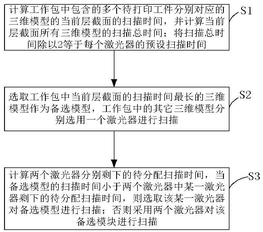
[0029] In order to achieve the above purpose, the present application provides a scanning path planning method based on dual lasers. The method includes: at most one workpiece to be printed in the current layer section of the work package is scanned by two lasers, and the current layer of the work package is scanned by two lasers. The other workpieces to be printed in the section are scanned by only one laser, and the workpieces to be printed that are scanned by two lasers belong to the contour, and the areas filled with the upper surface and the lower surface are scanned w...


PUM


Abstract

A scanning path planning method and device based on dual lasers, and a three-dimensional object manufacturing device, wherein the method includes: at most one workpiece to be printed in the current layer section of the work package is scanned by two lasers, and the current layer section of the work package is scanned by two lasers. Other workpieces to be printed are scanned by only one laser, and the workpieces to be printed that are scanned by two lasers are contours, and the areas filled on the upper surface and filled on the lower surface are scanned by the same laser. The scanning path planning method and device based on dual lasers and the three-dimensional object manufacturing equipment of the present invention reasonably allocate the scanning time of each laser by estimating the scanning time of the current layer section, reducing the idle waiting time of the lasers, that is, ensuring the scanning quality Under the premise of reducing the laser scanning waiting time as much as possible.

Description

technical field [0001] The present application relates to the technical field of additive manufacturing, in particular to a scanning path planning method and device based on dual lasers, and three-dimensional object manufacturing equipment. Background technique [0002] Additive manufacturing technology is an advanced manufacturing technology with distinctive features such as digital manufacturing, high flexibility and adaptability, direct CAD model drive, fast speed, and rich and diverse material types. tooling mold, so the application range is very wide. [0003] With the continuous development of additive manufacturing technology, the needs of users are also increasing, so a single laser is increasingly unable to meet all the needs of customers. Multi-laser full-coverage printing equipment, which can improve the production efficiency of additive manufacturing through multiple lasers. Each laser can manufacture each independent part in the sintering area separately, or it...

Claims


Application Information

Patent Timeline
Patent Type & Authority Patents(China)
IPC IPC(8): B29C64/268B29C64/282B29C64/386B29C64/393B33Y30/00B33Y50/00B33Y50/02
CPCB29C64/268B29C64/282B29C64/386B29C64/393B33Y30/00B33Y50/00B33Y50/02
Inventor 许小曙王朝龙杨大风曾维桥
Owner HUNAN FARSOON HIGH TECH CO LTD
Why Eureka
Try Eureka