Gas inlet structure for pressure swing adsorption drying machine and nitrogen oxygen generator

A technology of pressure swing adsorption and air intake structure, applied in the direction of oxygen/ozone/oxide/hydroxide, inorganic chemistry, nitrogen compounds, etc., can solve the problems of uncompact equipment structure, complicated production and control, and achieve The effect of simple installation, simple production and compact equipment structure

Pending Publication Date: 2019-12-03
FOSHAN TIANDI YUANYI PURIFICATION EQUIP
View PDF0 Cites 2 Cited by
  • Summary
  • Abstract
  • Description
  • Claims
  • Application Information

AI Technical Summary

Problems solved by technology

[0008] The invention provides a pressure swing adsorption dryer and an intake structure of a nitrogen and oxygen generator, which can improve the problems of too many valves, complicated production, complicated control and uncompact equipment structure

Method used


Image

  • Gas inlet structure for pressure swing adsorption drying machine and nitrogen oxygen generator
  • Gas inlet structure for pressure swing adsorption drying machine and nitrogen oxygen generator
  • Gas inlet structure for pressure swing adsorption drying machine and nitrogen oxygen generator

Examples


Embodiment 1

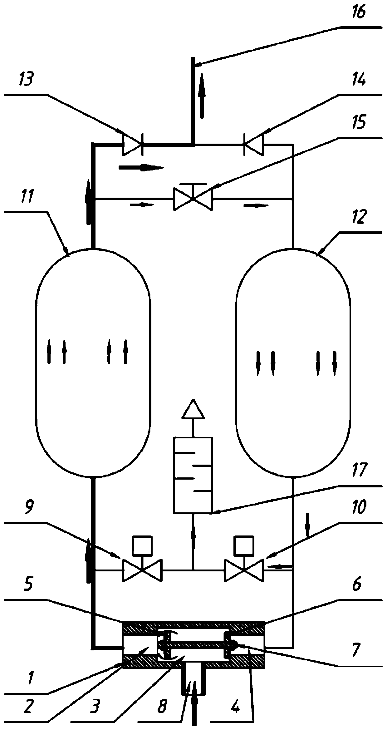
[0027] Embodiment 1: refer to figure 1 , the present invention provides a pressure swing adsorption dryer intake structure, or the structure of a nitrogen and oxygen generator, which includes a valve body 1, a first adsorption tank 11 and a second adsorption tank 12, the valve 1 penetrates through the A first cavity 2, a second cavity 3 and a third cavity 4 are provided in sequence, and the two ends of the second cavity 3 communicate with the first cavity 2 and the third cavity 4 respectively, and the second cavity The chamber 3 is connected to the gas inlet 8, and a valve core 7 is slidingly provided in the second cavity 3. The valve core 7 is preferably I-shaped, and the gas inlet 8 is connected to the middle part of the valve core 7. The two ends of the valve core 7 are respectively set A first valve plate 5 and a second valve plate 6 are used to open and close the vents at both ends of the second cavity 3, the first cavity 2 is connected to the lower part of the inner cav...

Embodiment 2

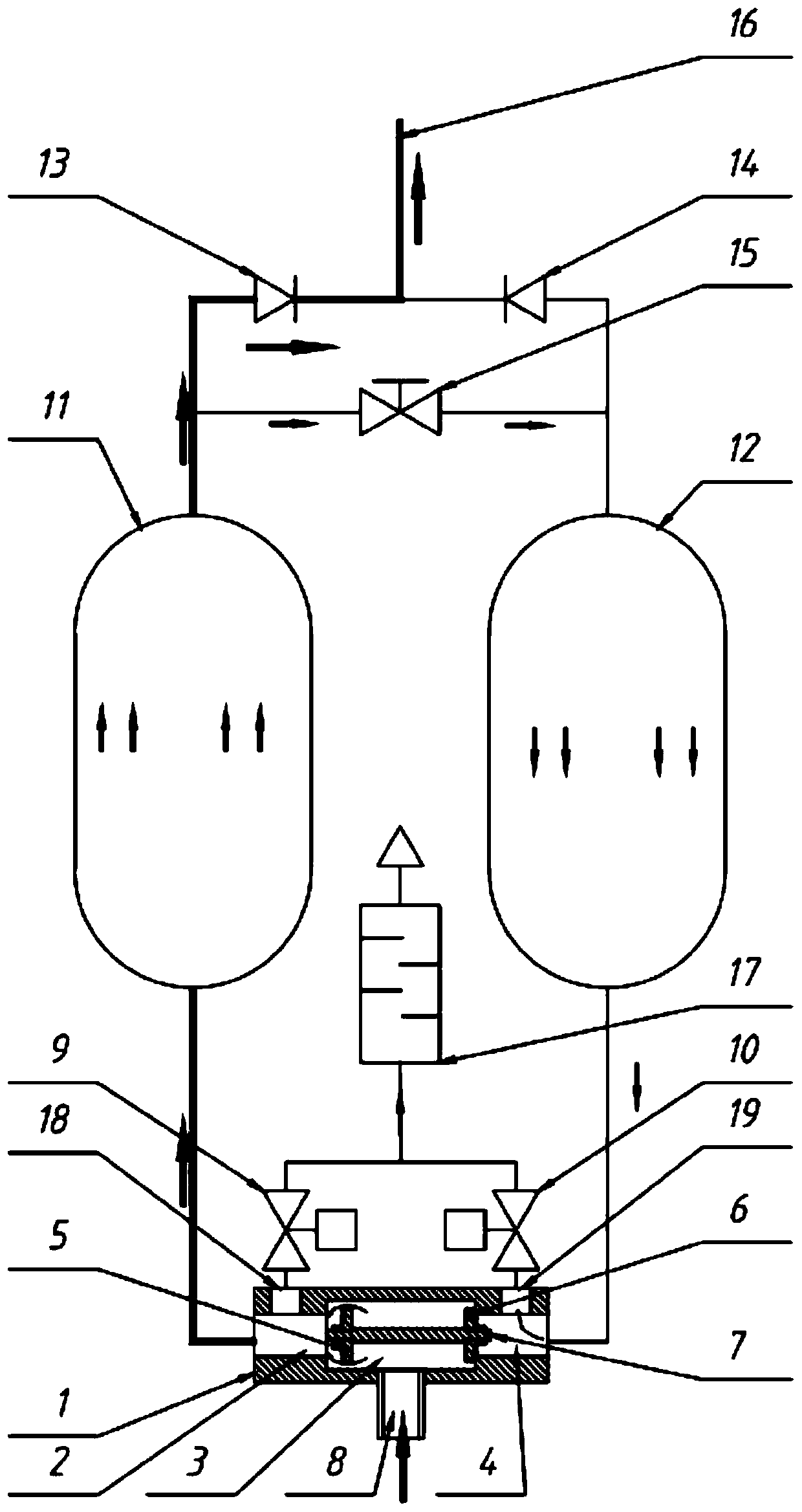
[0034] Embodiment 2: refer to figure 2 Compared with Embodiment 1, the difference is that: the first cavity 2 is also provided with a first outlet 18, the third cavity 4 is provided with a second outlet 19, and the first exhaust device 9 is connected to the first outlet. An outlet 18 to which the second exhaust device 10 is connected.

Embodiment 3

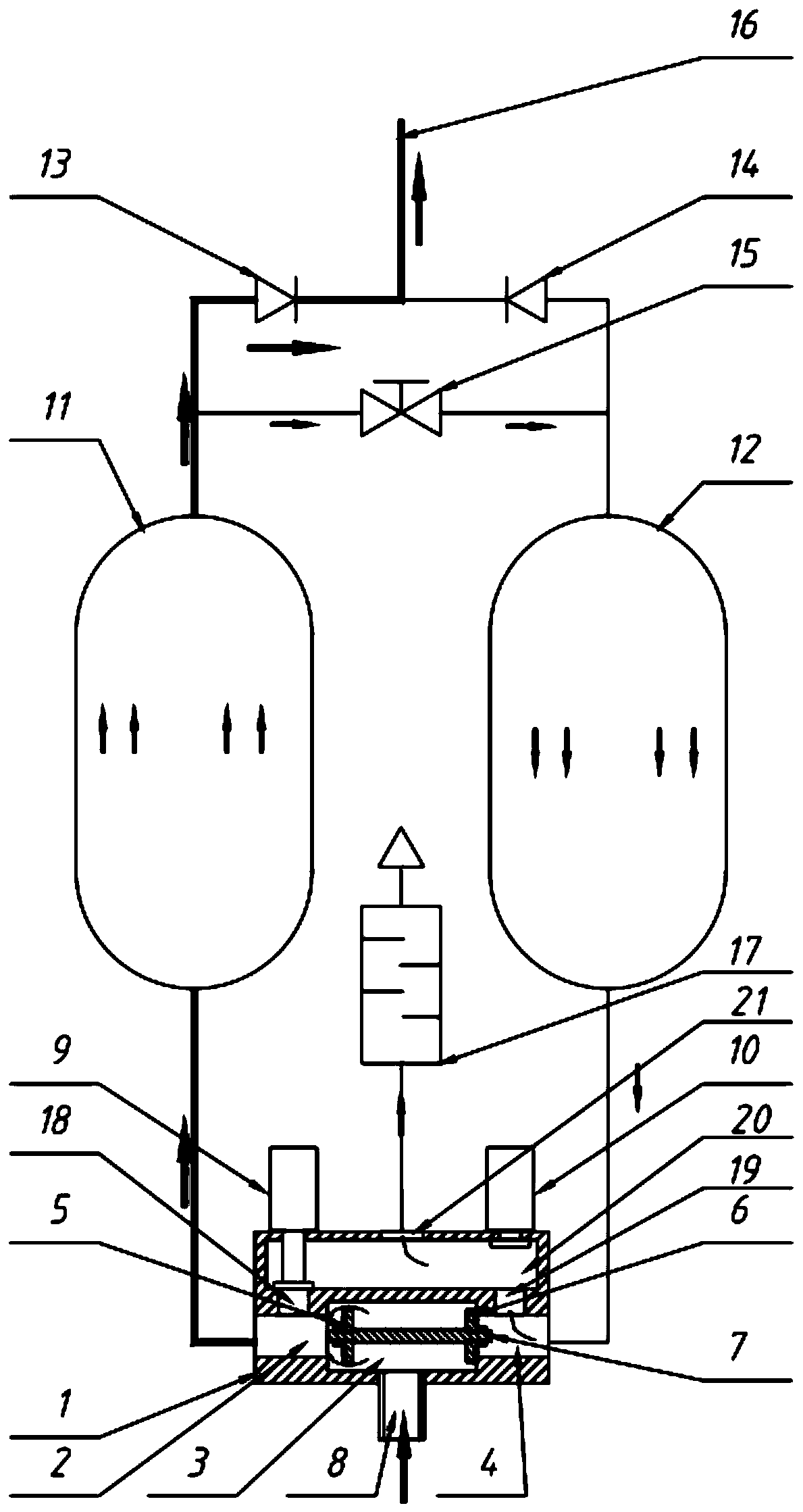
[0035] Embodiment 3: refer to image 3 , the present invention provides a pressure swing adsorption dryer intake structure, or the structure of a nitrogen and oxygen generator, which includes a valve body 1, a first adsorption tank 11 and a second adsorption tank 12, the valve 1 penetrates through the A first cavity 2, a second cavity 3 and a third cavity 4 are provided in sequence, and the two ends of the second cavity 3 communicate with the first cavity 2 and the third cavity 4 respectively, and the second cavity The chamber 3 is connected to the gas inlet 8, and a valve core 7 is slidingly provided in the second cavity 3. The valve core 7 is preferably I-shaped, and the gas inlet 8 is connected to the middle part of the valve core 7. The two ends of the valve core 7 are respectively set There are a first valve plate 5 and a second valve plate 6 for opening and closing the vents at both ends of the second cavity 3 . The valve body 1 is also provided with a fourth cavity 20 ...


PUM


Abstract

The invention provides a gas inlet structure for a pressure swing adsorption drying machine and nitrogen oxygen generator. The gas inlet structure comprises a valve body, a first adsorption tank and asecond adsorption tank; a second cavity is arranged in the valve body; two ends of the second cavity respectively communicates with a first cavity and a third cavity; the middle part of the second cavity communicates with a gas inlet; a valve core is slidably arranged in the second cavity; the first cavity communicates with an inner cavity of the first adsorption tank; the third cavity communicates with an inner cavity of the second adsorption tank; the first cavity is connected in parallel with a first exhaust device communicating with the outside; and the third cavity is connected in parallel with a second exhaust device communicating with the outside. According to the invention, two gas inlet valves are reduced, so that cost is saved; production and manufacturing are simple, valve bodies are few, pipelines are few, installation is simpler, control is simpler, and only two valves need to be controlled; and the structure of the gas inlet structure is compact.

Description

technical field [0001] The invention relates to the field of pressure swing adsorption, in particular to an intake structure of a pressure swing adsorption dryer or a nitrogen and oxygen generator. Background technique [0002] The intake structure of the existing adsorption dryer or nitrogen and oxygen generator, such as Figure 4 As shown, the first adsorption tank 11 and the second adsorption tank 12 are filled with adsorbents, which can absorb moisture under pressure (working state), and separate out moisture under no pressure (regeneration state). The two adsorption tanks work alternately, and their air intake structure includes four valves, which are respectively the first air intake valve 22, the second air intake valve 23, the first exhaust device 9, and the second exhaust device 10. The process is as follows: [0003] The regeneration process of the second adsorption tank 12 when the first adsorption tank 11 is working: the first intake valve 22 is opened, the seco...

Claims


Application Information

Patent Timeline
Patent Type & Authority Applications(China)
IPC IPC(8): C01B13/02C01B21/04
CPCC01B13/0259C01B21/045C01B2210/0062
Inventor 廖志远
Owner FOSHAN TIANDI YUANYI PURIFICATION EQUIP
Why Eureka
Try Eureka