
Microwave oven

A microwave oven and food technology, applied in the field of microwave ovens, can solve problems such as difficult to accurately detect and control the cooking state

Inactive Publication Date: 2003-04-09
LG ELECTRONICS INC
View PDF0 Cites 0 Cited by
  • Summary
  • Abstract
  • Description
  • Claims
  • Application Information

AI Technical Summary

Problems solved by technology

In both cases, it is difficult to precisely detect and control the cooking status since the output signal varies with the distance between the sensor and the food

Method used


Image

  • Microwave oven
  • Microwave oven
  • Microwave oven

Examples


Embodiment Construction

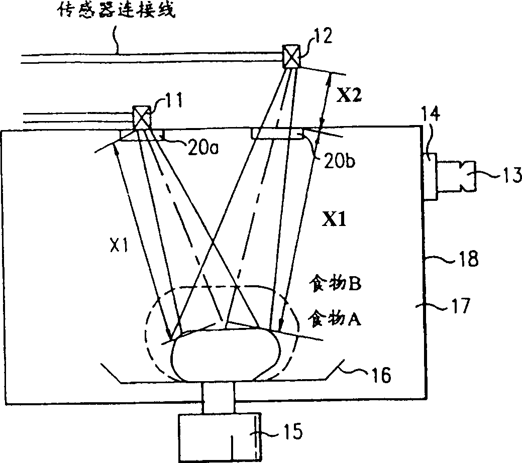
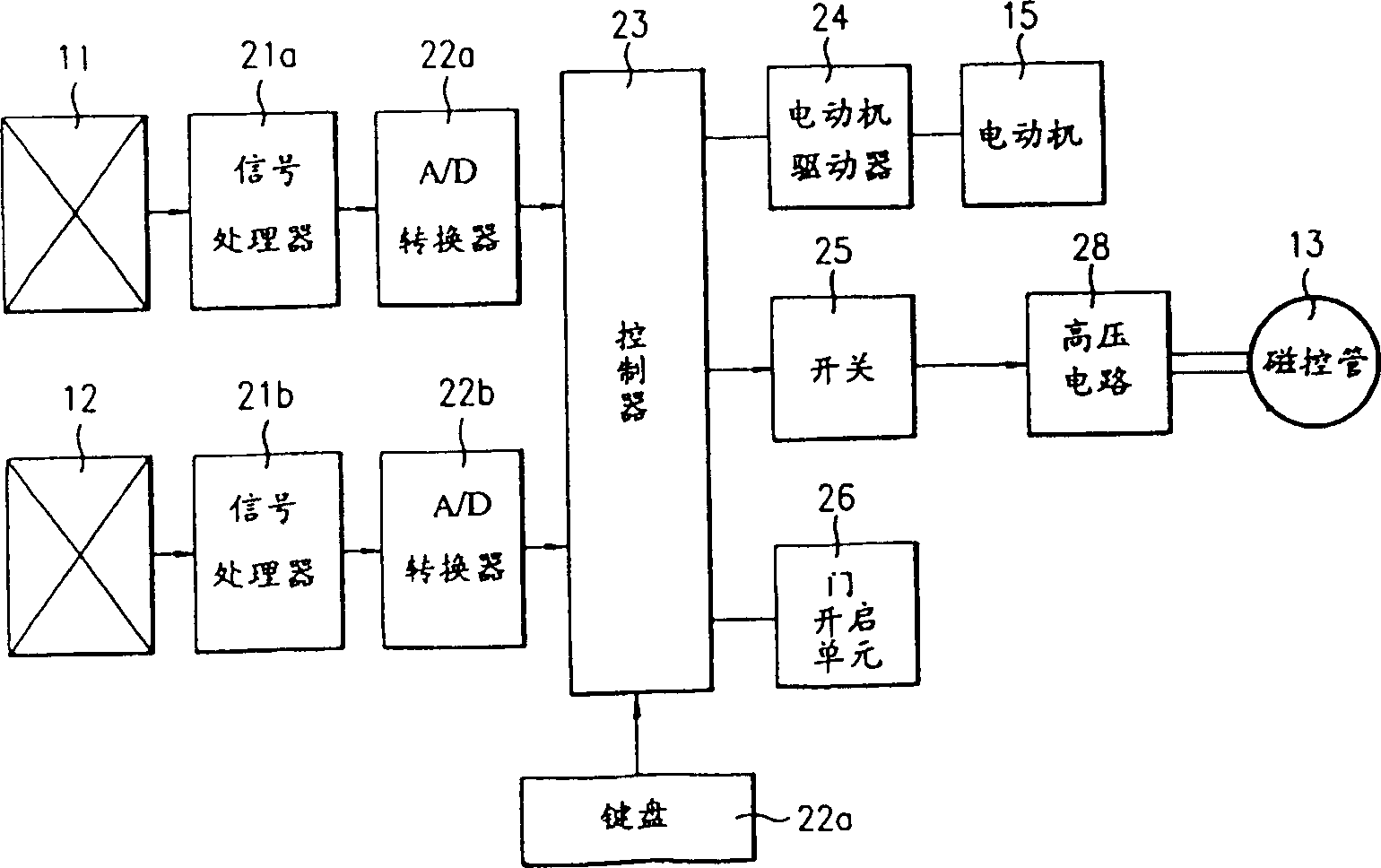
[0015] Such as figure 2 As shown, the microwave oven according to the present invention includes: the first and the second infrared sensors 11 and 12 for detecting the heat radiation emitted from the heated food; Signal processors 21a and 21b to obtain accurate food surface temperature independent of offset in distance between each sensor; analog / digital (A / D) converters 22a and 22b to convert analog signals into digital signals; The signal converted by the A / D converters 22a and 22b then recognizes the food state and controls the controller 23 of the motor 15 and the magnetron 13 according to the cooking method; 25; a high-voltage circuit 28 for operating the magnetron according to the on / off action of the switch 25; and a keyboard 27 for selecting food menus or cooking methods.

[0016] In addition, such as indicating the internal structure of the microwave oven figure 1 As shown, this microwave oven has an infrared sensor which transmits a signal to a cooking state detec...


PUM


Abstract

The present invention provides a microwave oven including at least two sensors for detecting heat rays emitted from the food which is being heated, a signal processor for obtaining a precise surface temperature of food, irrespective of the deviation of distances between the sensors and food, using output signals from the sensors, and a controller for receiving the output signal of the signal processor to recognize the cooking status of the food and controlling the heating of the food in accordance with the recognized cooking status.

Description

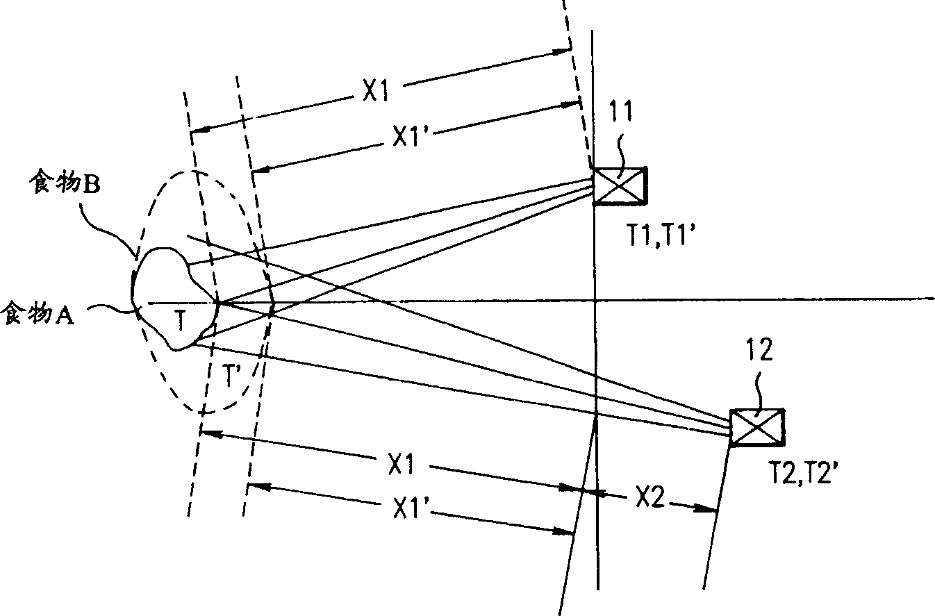
technical field [0001] The invention relates to a microwave oven, in particular to a microwave oven for precise cooking control by using a remote sensor to detect the radiation temperature of the food surface and compensating the distance between the food and the sensor. Background technique [0002] Ordinary microwave ovens use temperature detection sensors, humidity detection sensors, steam detection sensors or weight detection sensors to detect cooking status, and thus perform automatic cooking, for example: in order to detect the amount of food, first measure the weight of the food and then decide when the cooking is complete . In addition, the temperature, humidity, or gas at a point in time may be detected to calculate the time to maintain cooking for cooking. [0003] However, ordinary microwave ovens have a limitation when measuring humidity, gas, steam, or changes in the ambient temperature of food for cooking. Specifically, in the case of thaw...

Claims


Application Information

Patent Timeline
IPC IPC(8): F24C7/02H05B6/68
CPCH05B6/6455F24C7/08
Inventor 夫钟郁郑光均
Owner LG ELECTRONICS INC
Learn More