pressure fastener

A fastener and pressure technology, applied in the direction of threaded fasteners, locking fasteners, connecting components, etc., can solve the problems of easy nut retraction and difficulty for workers to fasten

Active Publication Date: 2021-01-01
XUCHANG SIDA ELECTRIC POWER EQUIP
View PDF5 Cites 0 Cited by
  • Summary
  • Abstract
  • Description
  • Claims
  • Application Information

AI Technical Summary

Problems solved by technology

[0007] In view of the above situation, in order to overcome the defects of the prior art, the present invention provides a pressure fastener, which effectively solves the problems that the nut is easy to retreat and the worker is difficult to fasten when fixing the drainage plate.

Method used


Image

  • pressure fastener
  • pressure fastener
  • pressure fastener

Examples


Embodiment 1

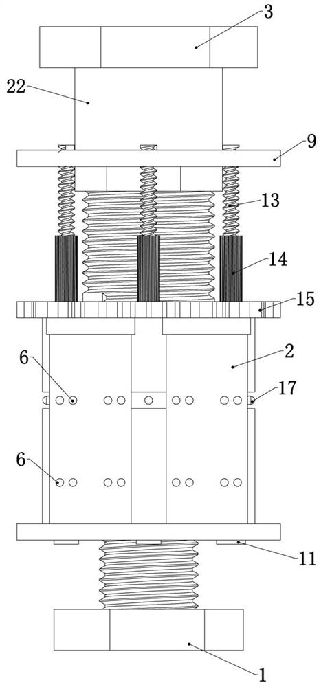
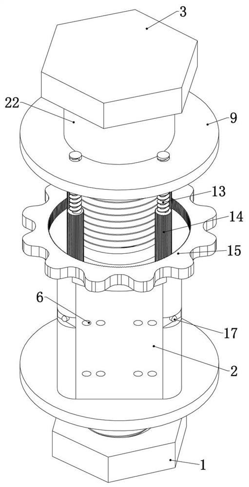
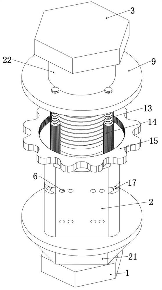
[0033] Embodiment 1, the present invention is a pressure fastener, including a bolt 1, which is characterized in that the external thread of the bolt 1 is provided with a threaded sleeve 2, and the outer wall of the upper end of the threaded sleeve 2 is provided with threads. The upper threaded sleeve of the threaded sleeve 2 is provided with a nut 3, and the lower end of the nut 3 is fixedly connected with an elastic member 4 arranged inside the threaded sleeve 2. The elastic member 4 can be a spring 18, or can be Spring steel sleeves, or even common elastic parts 4 such as air pressure devices or oil pressure devices, after the two drain plates clamp the wires, pass the bolt 1 through the fixing holes of the two drain plates, and set the threaded sleeve 2 on the Screw on the bolt 1 and tighten it, and then tighten the nut 3. At this time, the nut 3 compresses the elastic member 4, and the restoring force of the elastic member 4 acts upward and downward at the same time. Under...

Embodiment 2

[0037] Embodiment 2. On the basis of Embodiment 1, this embodiment provides a specific structure, so that the threaded sleeve 2 can be closely connected with the drainage plate in contact. Specifically, the lower end of each air passage 5 is A booster hole 10 is provided, and each of the booster holes 10 is coaxially provided with a rubber ring 11 fixedly connected to the bottom of the threaded sleeve 2. In the specific use of this embodiment, the threaded sleeve 2 is placed on the Bolt 1 is screwed on and stopped until the rubber ring 11 is in contact with the upper drain plate, or it can also be screwed one more turn to stop after the rubber ring 11 contacts the upper drain plate, so that the rubber ring 11 and the drain plate are in close contact. To prevent air leakage, after that, turn the nut 3 to drive the lower piston 8 to move upward, so that the drainage plate can be firmly sucked under the threaded sleeve 2 through the booster hole 10, so that the device and the drai...

Embodiment 3

[0038]Embodiment 3. On the basis of Embodiment 1, this embodiment provides a specific way in which the upper piston 7 is connected to the push ring 9, so that the initial position of the upper piston 7 can be adjusted. Specifically, the upper piston 7 on the push ring 9 There are several threaded holes 12, and the upper end of each upper piston 7 is rotatably connected with a screw 13, and the upper end of each said screw 13 cooperates with several threaded holes 12 on the push ring 9 respectively, and each said screw The middle part of 13 is coaxially fixedly connected with a screw gear 14, and the outside of the threaded sleeve 2 is coaxially rotatably connected with an outer ring gear 15 meshing with several of the screw gears 14 at the same time, and the outer ring gear 15 rotates It can drive some screw gears 14 meshed with it to rotate, and drive the corresponding screw rod 13 to rotate. At this time, because the push ring 9 is rotated and connected to the nut 3, and the ...


PUM


Abstract

The invention relates to a pressure fastener, and effectively solves the problems that a nut is easy to rollback and a worker cannot easily fasten the nut when a drainage plate is fixed. According tothe technical scheme, a bolt is included and is characterized in that a threaded sleeve is sleeved outside the bolt in a threaded mode, threads are formed on the outer wall of the upper end of the threaded sleeve, and a nut is sleeved on the upper portion of the threaded sleeve in a threaded mode. An elastic piece is arranged below the nut, a plurality of air channels are formed in the outer portion of the threaded sleeve, two sets of vent holes are vertically formed in the two sides of each air channel side by side, an upper piston is connected into each air channel in an up-down sliding mode, and each upper piston is connected with a lower piston which is connected into the corresponding air channel in an up-down sliding mode through a connecting rod mechanism arranged in the corresponding air channel. A pushing ring is coaxially and rotationally connected to the outer part of the nut; each upper piston is fixedly connected with the pushing ring through a rod piece; the pressure fastener is simple in structure, the pre-tightening force between the bolt and the fastener and between a fastening clamp and the nut is effectively increased, the fastening effect is good, the nut is notprone to retreating, the operation is easy, and practicability is high.

Description

technical field [0001] The invention relates to the technical field of fasteners, in particular to pressure fasteners. Background technique [0002] Between two high-voltage transmission lines or between two transmission lines near the transformer, it is usually necessary to clamp and fix the two transmission lines through two diversion plates. In this process, bolts are usually used to clamp the two diversion plates. However, in this process, the following problems often exist: [0003] 1. After the bolts and nuts are used for a period of time, the nuts are prone to retreat, resulting in the reduction of the compression force of the drainage plate on the wires and failure; [0004] 2. Because the drainage plate is mostly made of aluminum alloy, when the worker twists the nut, in order to prevent the nut from loosening and retreating, it is easy to use a lot of force, which will cause the drainage plate to deform and cause failure. [0005] Therefore, continue to provide a...

Claims


Application Information

Patent Timeline
Patent Type & Authority Patents(China)
IPC IPC(8): F16B5/02F16B39/284F16B39/28H02G7/05
CPCF16B5/0241F16B5/0266F16B39/28F16B39/284H02G7/05
Inventor 杨再登陈瑞斌古亚军崔晨阳赵超鹏卫亮昆
Owner XUCHANG SIDA ELECTRIC POWER EQUIP
Why Eureka
Try Eureka