A flow control valve
A technology of flow control valve and valve body, applied in the field of control valve, can solve the problems of increasing labor intensity, increasing human workload, pipeline damage, etc., and achieve the effects of reducing labor intensity, reducing speed, and reducing water pressure
- Summary
- Abstract
- Description
- Claims
- Application Information
AI Technical Summary
Problems solved by technology
Method used
Image

Examples
Embodiment 1
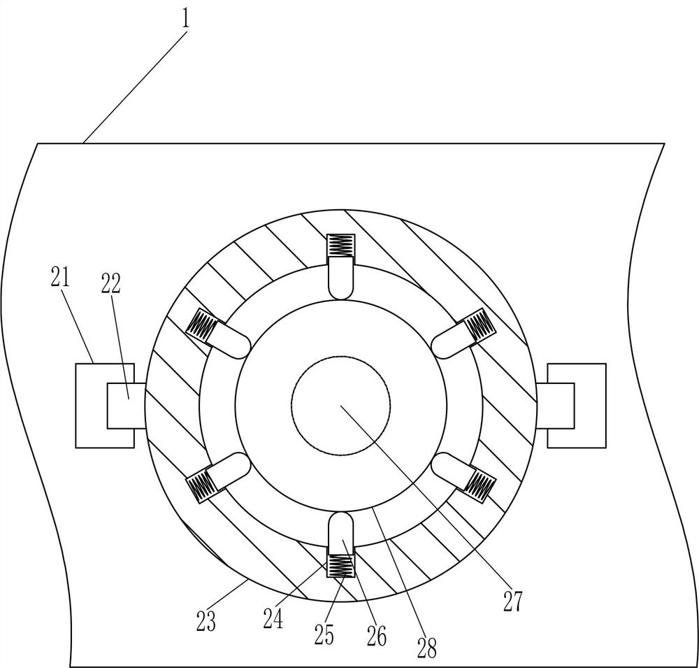
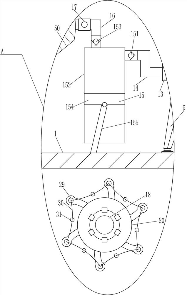
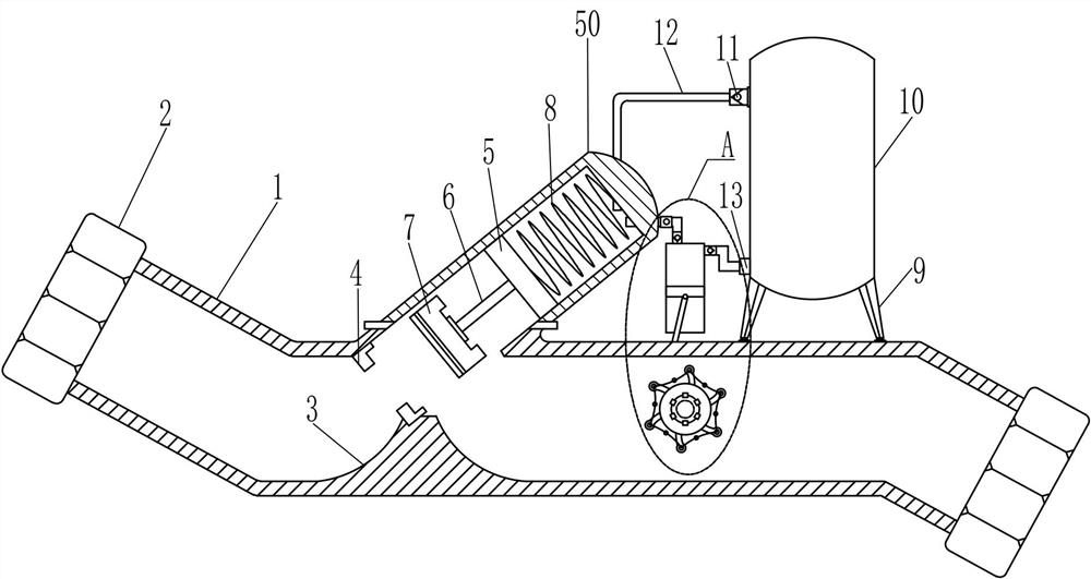
[0018] A flow control valve such as Figure 1-3 As shown, it includes valve body 1, connecting nut 2, valve seat 3, ferrule 4, valve tube 50, first piston 5, connecting rod 6, chuck 7, first compression spring 8, leg 9, hydraulic oil Tank 10, first one-way valve 11, return hose 12, liquid outlet pipe 13, first hard pipe 14, pumping device 15, second hard pipe 16, one-way ventilation valve 17, first rotating shaft 18, The second push rod 19 and the water wheel 20, the left and right sides of the valve body 1 are provided with connecting nuts 2, the bottom left side in the valve body 1 is connected with the valve seat 3, the top left side in the valve body 1 is connected with the valve seat 3 A ferrule 4 is connected between the tops of the valve body 1, a valve pipe 50 is provided on the left side of the top of the valve body 1, and the first piston 5 is slidably located in the valve pipe 50. A connecting rod 6 is installed on the bottom of the first piston 5, and the connectin...
Embodiment 2
[0020] A flow control valve such as Figure 1-3 As shown, it includes valve body 1, connecting nut 2, valve seat 3, ferrule 4, valve tube 50, first piston 5, connecting rod 6, chuck 7, first compression spring 8, leg 9, hydraulic oil Tank 10, first one-way valve 11, return hose 12, liquid outlet pipe 13, first hard pipe 14, pumping device 15, second hard pipe 16, one-way ventilation valve 17, first rotating shaft 18, The second push rod 19 and the water wheel 20, the left and right sides of the valve body 1 are provided with connecting nuts 2, the bottom left side in the valve body 1 is connected with the valve seat 3, the top left side in the valve body 1 is connected with the valve seat 3 A ferrule 4 is connected between the tops of the valve body 1, a valve pipe 50 is provided on the left side of the top of the valve body 1, and the first piston 5 is slidably located in the valve pipe 50. A connecting rod 6 is installed on the bottom of the first piston 5, and the connectin...
Embodiment 3
[0023] A flow control valve such as Figure 1-4As shown, it includes valve body 1, connecting nut 2, valve seat 3, ferrule 4, valve tube 50, first piston 5, connecting rod 6, chuck 7, first compression spring 8, leg 9, hydraulic oil Tank 10, first one-way valve 11, return hose 12, liquid outlet pipe 13, first hard pipe 14, pumping device 15, second hard pipe 16, one-way ventilation valve 17, first rotating shaft 18, The second push rod 19 and the water wheel 20, the left and right sides of the valve body 1 are provided with connecting nuts 2, the bottom left side in the valve body 1 is connected with the valve seat 3, the top left side in the valve body 1 is connected with the valve seat 3 A ferrule 4 is connected between the tops of the valve body 1, a valve pipe 50 is provided on the left side of the top of the valve body 1, and the first piston 5 is slidably located in the valve pipe 50. A connecting rod 6 is installed on the bottom of the first piston 5, and the connecting...
PUM
 Abstract
Description
Claims
Application Information
 - R&D Engineer
- R&D Manager
- IP Professional
- Industry Leading Data Capabilities
- Powerful AI technology
- Patent DNA Extraction
Browse by: Latest US Patents, China's latest patents, Technical Efficacy Thesaurus, Application Domain, Technology Topic.
© 2024 PatSnap. All rights reserved.Legal|Privacy policy|Modern Slavery Act Transparency Statement|Sitemap