
Variable inner diameter flange assembly

A flange and inner diameter technology, which is applied in the field of variable inner diameter flange components, can solve the problems of labor waste, capacity waste, and increased production costs, and achieve the effects of improving equipment utilization, reducing production costs, and reducing production change time

Pending Publication Date: 2019-12-03
CHINAUST PLASTICS CORP
View PDF0 Cites 1 Cited by
  • Summary
  • Abstract
  • Description
  • Claims
  • Application Information

AI Technical Summary

Problems solved by technology

With the increase in the number of production changes, a large amount of capacity waste, labor waste and production cost increase

Method used


Image

  • Variable inner diameter flange assembly
  • Variable inner diameter flange assembly
  • Variable inner diameter flange assembly

Examples


Embodiment Construction

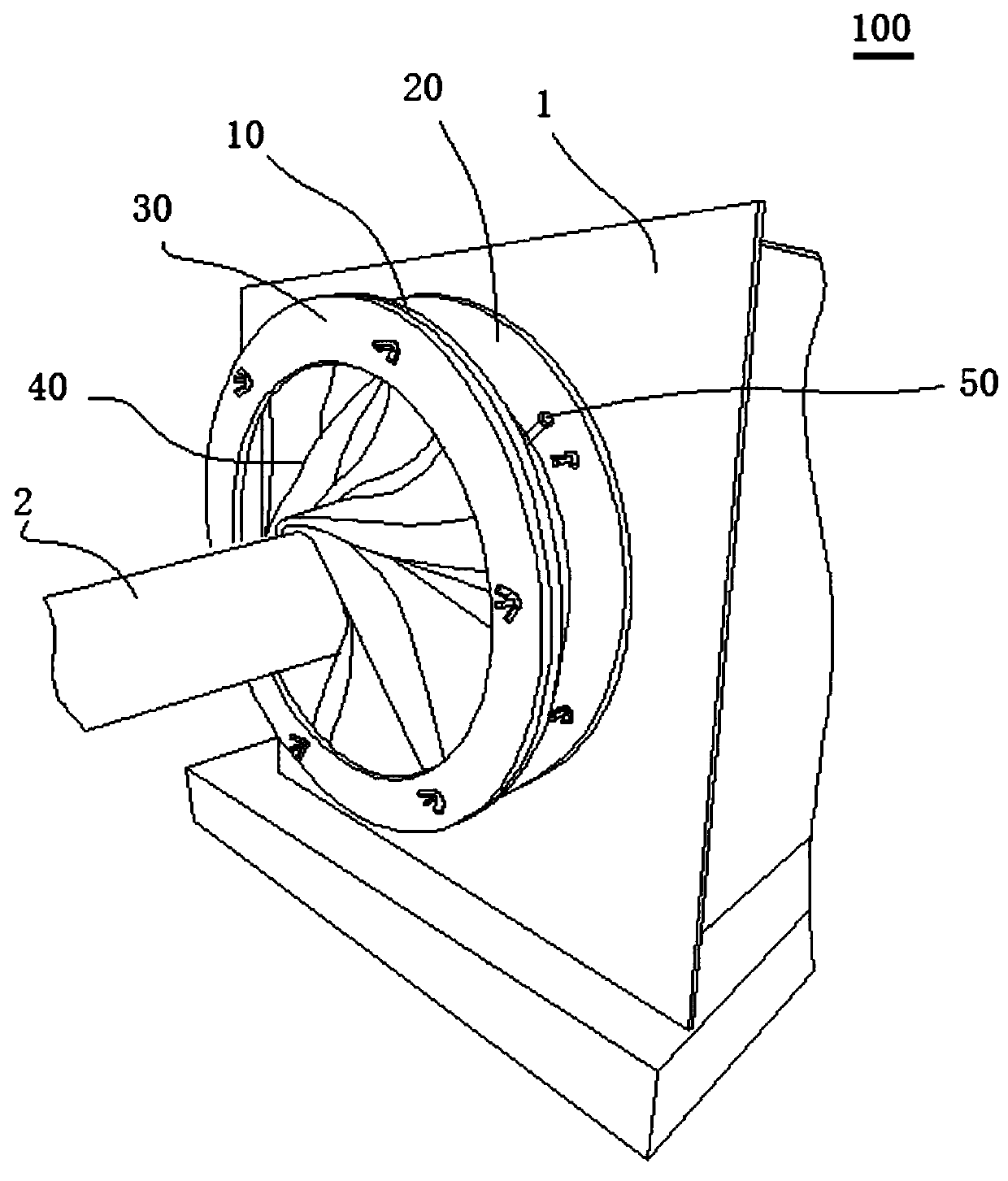
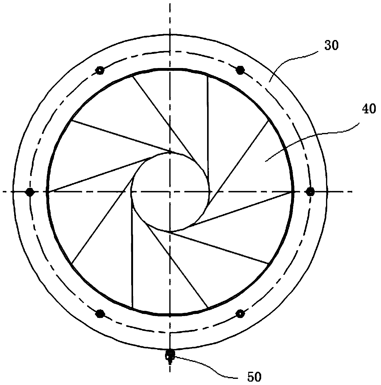
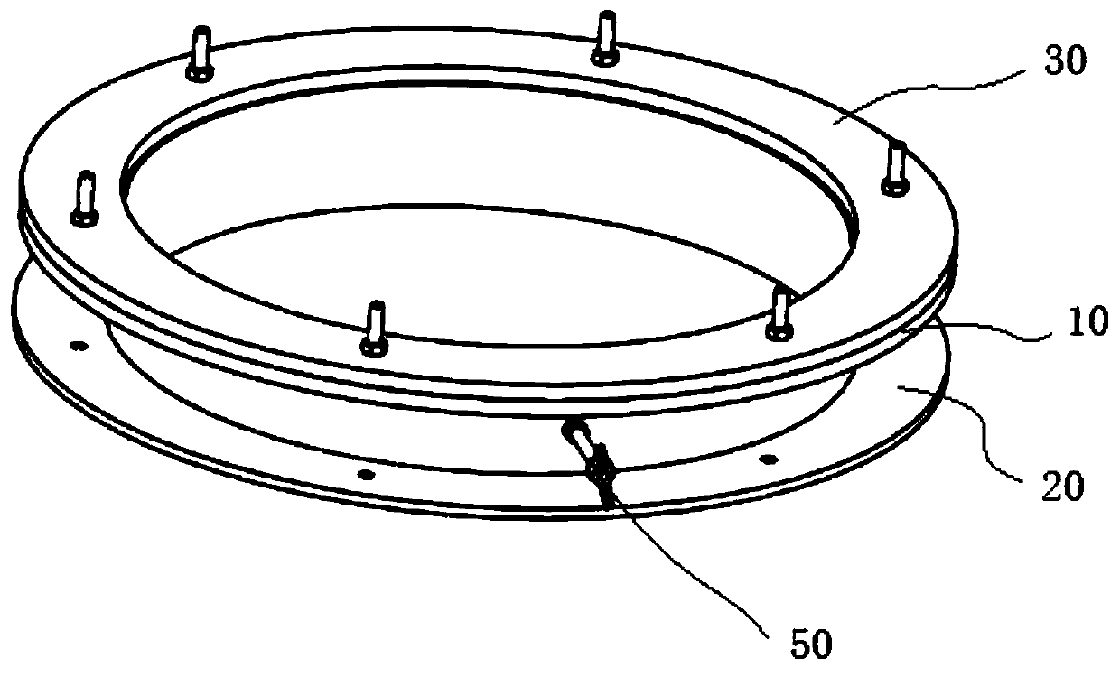
[0042] figure 1 It is a schematic perspective view of a variable inner diameter flange assembly according to an embodiment of the present application. figure 2 Yes figure 1 A schematic front view of the variable inner diameter flange assembly shown. image 3 Yes figure 1 A schematic front view of the variable inner diameter flange assembly shown with the flexible sleeve removed. Figure 4 Yes figure 1 A schematic back view of the variable inner diameter flange assembly shown with the flexible sleeve removed. Figure 5 Yes figure 1 The shown schematic assembly drawing of the variable inner diameter flange assembly with the flexible sleeve removed. Image 6 Yes Figure 5 A schematic partial enlarged view at middle A. Picture 10 Yes Figure 5 A schematic partial enlarged view when the flexible sleeve is installed at center A.

[0043] Such as figure 1 Shown, see also Figure 2-Figure 6 This embodiment provides a variable inner diameter flange assembly 100, which includes an upper fl...


PUM


Abstract

The invention discloses a variable inner diameter flange assembly, and relates to a production auxiliary tool. The assembly comprises an upper flange, a lower flange, an external pressure flange and aflexible sleeve. The lower flange and the upper flange are oppositely arranged, and the lower flange sleeves the upper flange, so that the lower flange and the upper flange can freely rotate around the axes thereof. The external pressure flange is arranged at the upper flange, the flexible sleeve is lined in the lower flange, one end of the flexible sleeve is fixed between the upper flange and awater tank, and the other end is fixed between the upper flange and the external pressure flange. The variable inner diameter flange assembly is installed at the water tank, by rotating the upper flange, an overhanging part of the flexible sleeve located in the lower flange is driven by the upper flange to be twisted and deformed to be tightly hooped on the surface of a pipe, and therefore the free scaling of the inner diameter of the variable inner diameter flange assembly is achieved. And the flange assembly with the variable inner diameter can be suitable for the production lines of all specifications through scaling the size. During the production line replacement, the replacement of the flanges at the two ends of the water tank can be eliminated, the flange replacement time is eliminated, the overall production replacement time is shortened, the equipment utilization rate is greatly increased, and the production cost is reduced.

Description

Technical field [0001] This application relates to auxiliary tooling used in the cooling process of pipe production, in particular to a variable inner diameter flange assembly. Background technique [0002] In the prior art, various specifications of plastic pipes are produced by extruders. Generally, the surface temperature of the pipe after extrusion is very high, and spray cooling equipment is required for cooling and shaping. The production line usually sets 5 spray equipment for cooling. In order to ensure that the cooling medium in the spraying equipment is not taken out of the spraying equipment by the pipes and causing waste, usually flanges corresponding to the pipe specifications are installed at both ends of each spraying equipment. Rubber pads are installed at the inner diameter of the flanges. The film pad is in 360-degree contact with the pipe, and the spraying medium attached to the surface of the pipe is cleaned to ensure that the reuse of the spraying medium is ...

Claims


Application Information

Patent Timeline
Patent Type & Authority Applications(China)
IPC IPC(8): F16L23/08
CPCF16L23/08
Inventor 孙朝侯书宾马金华葛红玉黄京城吴晋冀李瑜冯超刘晓举崔成保鲁广讯崔阳
Owner CHINAUST PLASTICS CORP
Learn More