
Bearing cylinder type main supporting structure of large off-axis three-mirror space remote sensing camera

An off-axis three-mirror, remote sensing camera technology, applied in the field of space optical remote sensing, can solve the problems of excessive size envelope and low support rigidity, achieve the effect of reducing quality, ensuring structural rigidity, and improving structural utilization

Active Publication Date: 2019-12-03
CHANGGUANG SATELLITE TECH CO LTD
View PDF6 Cites 2 Cited by
  • Summary
  • Abstract
  • Description
  • Claims
  • Application Information

AI Technical Summary

Problems solved by technology

[0005] The present invention aims to solve the existing problems of low support rigidity and excessively large size envelope of the camera mirror assembly caused by the characteristics of the long focal length and wide field of view of the optical system, which cause the main, third, and folding mirrors of the camera to have large aspect ratios and large masses. A load-bearing cylinder-type main support structure of a large off-axis three-mirror space remote sensing camera

Method used


Image

  • Bearing cylinder type main supporting structure of large off-axis three-mirror space remote sensing camera
  • Bearing cylinder type main supporting structure of large off-axis three-mirror space remote sensing camera
  • Bearing cylinder type main supporting structure of large off-axis three-mirror space remote sensing camera

Examples


specific Embodiment approach 1

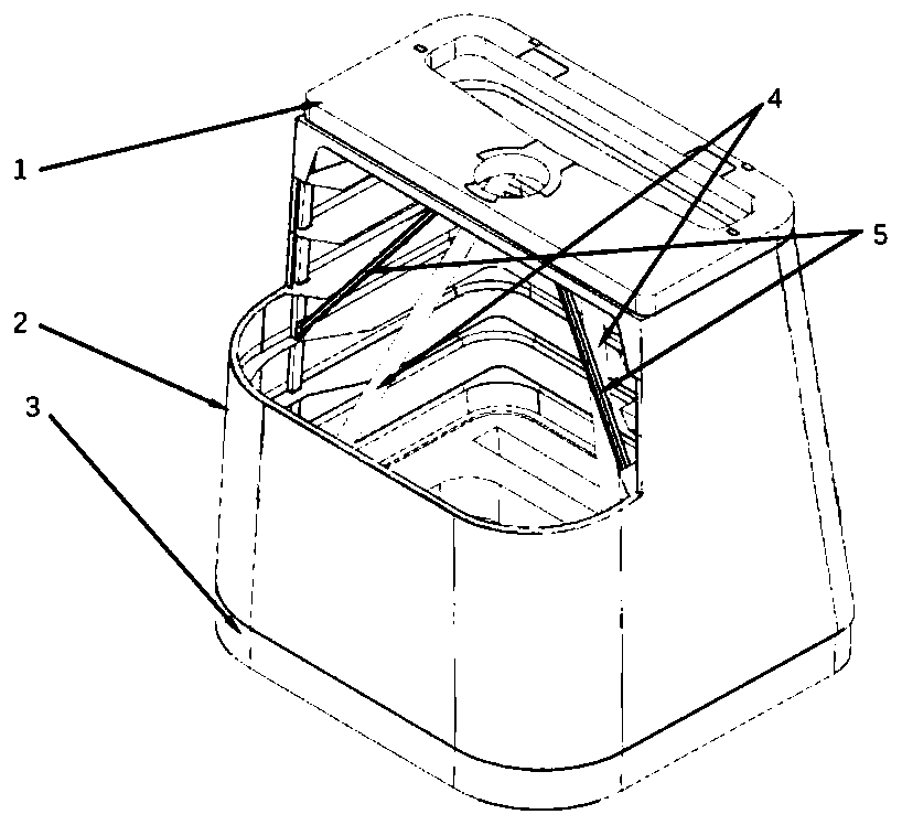
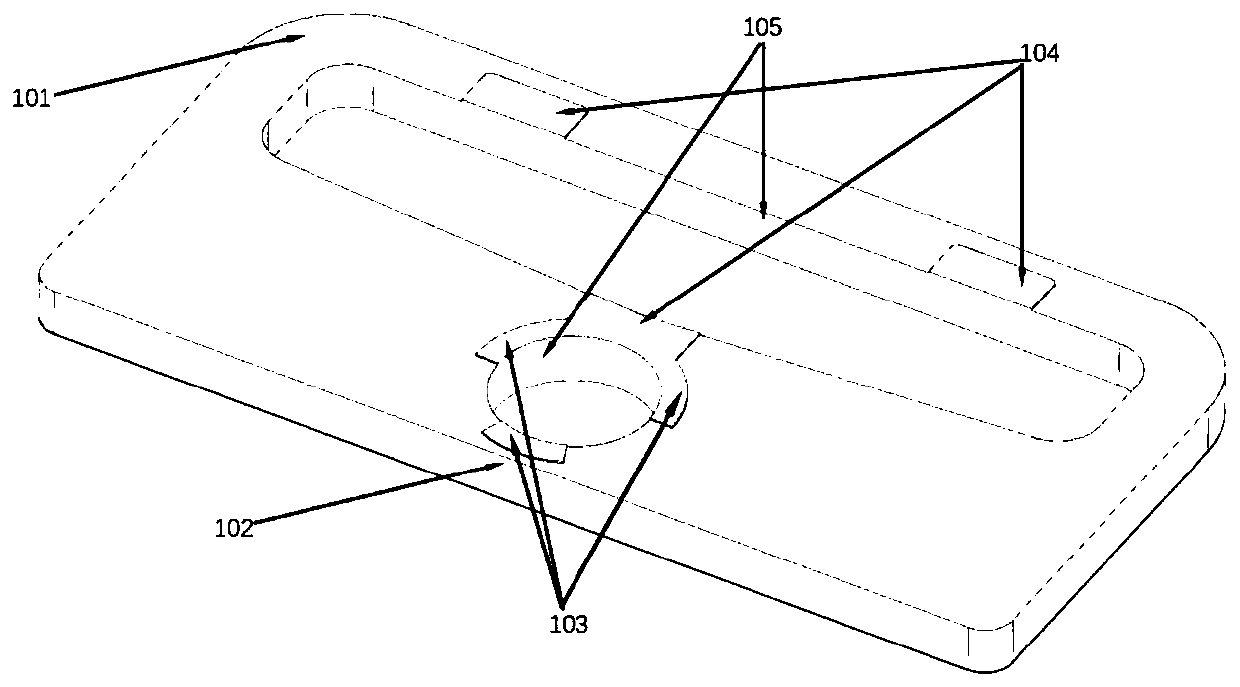
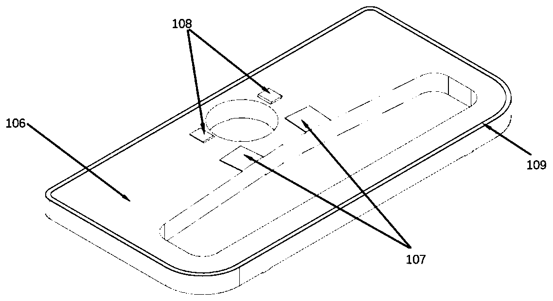
[0024] Specific implementation mode one, combination Figure 1 to Figure 8 To explain this embodiment, the main supporting structure of the bearing cylinder of a large off-axis three-mirror space remote sensing camera includes a front frame 1, a main bearing cylinder 2, a rear frame 3, a truss rod assembly 4, and a stiffener assembly 5. The main bearing tube 2 is connected with the front frame 1 and the rear frame 3 by screws; the truss rod assembly 4 includes two truss rods arranged symmetrically, and the upper end of each truss rod is positioned and connected with the front frame, and the The lower end is positioned and connected with the rear frame; the lower end of the stiffener assembly 5 is connected with the main bearing tube and the upper end of the stiffener assembly 5 and the front frame 1 are connected by a titanium alloy joint;

[0025] Combine figure 2 with image 3 To illustrate this embodiment, the main structure of the front frame 1 includes: a front frame upper ...


PUM


Abstract

The invention discloses a bearing cylinder type main supporting structure of a large off-axis three-mirror space remote sensing camera. The invention relates to the technical field of space optical remote sensing, and solves the problems of low support rigidity and overlarge size envelope of a camera mirror assembly caused by large length-width ratio and large mass of main, third and folding mirrors of a camera due to the characteristics of long focal length and wide field of view of an optical system in the prior art, and the structure comprises a front frame, a rear frame, a main bearing cylinder, a truss rod assembly and a reinforcing rib assembly, the main bearing cylinder is connected with the front frame and the rear frame through screws. The truss rod assembly comprises two truss rods which are symmetrically arranged, the upper end of each truss rod is in positioning connection with the front frame, and the lower end of each truss rod is in positioning connection with the rear frame; the lower end of the reinforcing rib assembly is connected with the main bearing cylinder and the upper end of the reinforcing rib assembly is connected with the front frame through titanium alloy joints; the front frame, the force bearing cylinder, the rear frame and the truss rod joints are all in a plane assembly form, so that the assembly difficulty is greatly reduced, and meanwhile, theproduction period and the manufacturing cost are greatly reduced.

Description

Technical field [0001] The invention relates to the technical field of space optical remote sensing, in particular to a force-bearing cylindrical main support structure of a large off-axis three-reflection camera. Background technique [0002] At present, a large off-axis three-reflection space remote sensing camera with a long focal length and a wide field of view requires its main supporting structure to be light in weight, high in rigidity and good in stability. Large-scale off-axis three-mirror space remote sensing cameras mostly use a truss-pole-type main support structure, which has the disadvantages of heavy mass and large camera envelope size. The use of a bearing cylindrical main support structure can reduce the camera's envelope size while increasing the camera Lightweight rate. The support form of the bearing cylinder has the characteristics of small envelope size, so it can be launched with a smaller rocket, which greatly reduces the launch cost. The disadvantage of...

Claims


Application Information

Patent Timeline
IPC IPC(8): F16M11/00G03B17/56
CPCF16M11/00G03B17/56
Inventor 魏磊刘林鹤贾学志张雷
Owner CHANGGUANG SATELLITE TECH CO LTD
Learn More