Turbulence flow device, shunt assembly and air conditioning unit

A technology of turbulence device and flow divider, which is applied in the direction of refrigeration components, refrigerators, mechanical equipment, etc., and can solve the problem of uneven liquid separation

Pending Publication Date: 2019-12-03
GREE ELECTRIC APPLIANCES INC
View PDF0 Cites 9 Cited by
  • Summary
  • Abstract
  • Description
  • Claims
  • Application Information

AI Technical Summary

Problems solved by technology

[0004] The embodiment of the present invention provides a turbulence device, a flow splitter assembly and an air conditioning unit to solve the technical problem of uneven liquid separation in the flow splitter in the prior art

Method used


Image

  • Turbulence flow device, shunt assembly and air conditioning unit
  • Turbulence flow device, shunt assembly and air conditioning unit
  • Turbulence flow device, shunt assembly and air conditioning unit

Examples


Embodiment Construction

[0031] In order to make the object, technical solution and advantages of the present invention clearer, the present invention will be described in further detail below in conjunction with the embodiments and accompanying drawings. Here, the exemplary embodiments and descriptions of the present invention are used to explain the present invention, but not to limit the present invention.

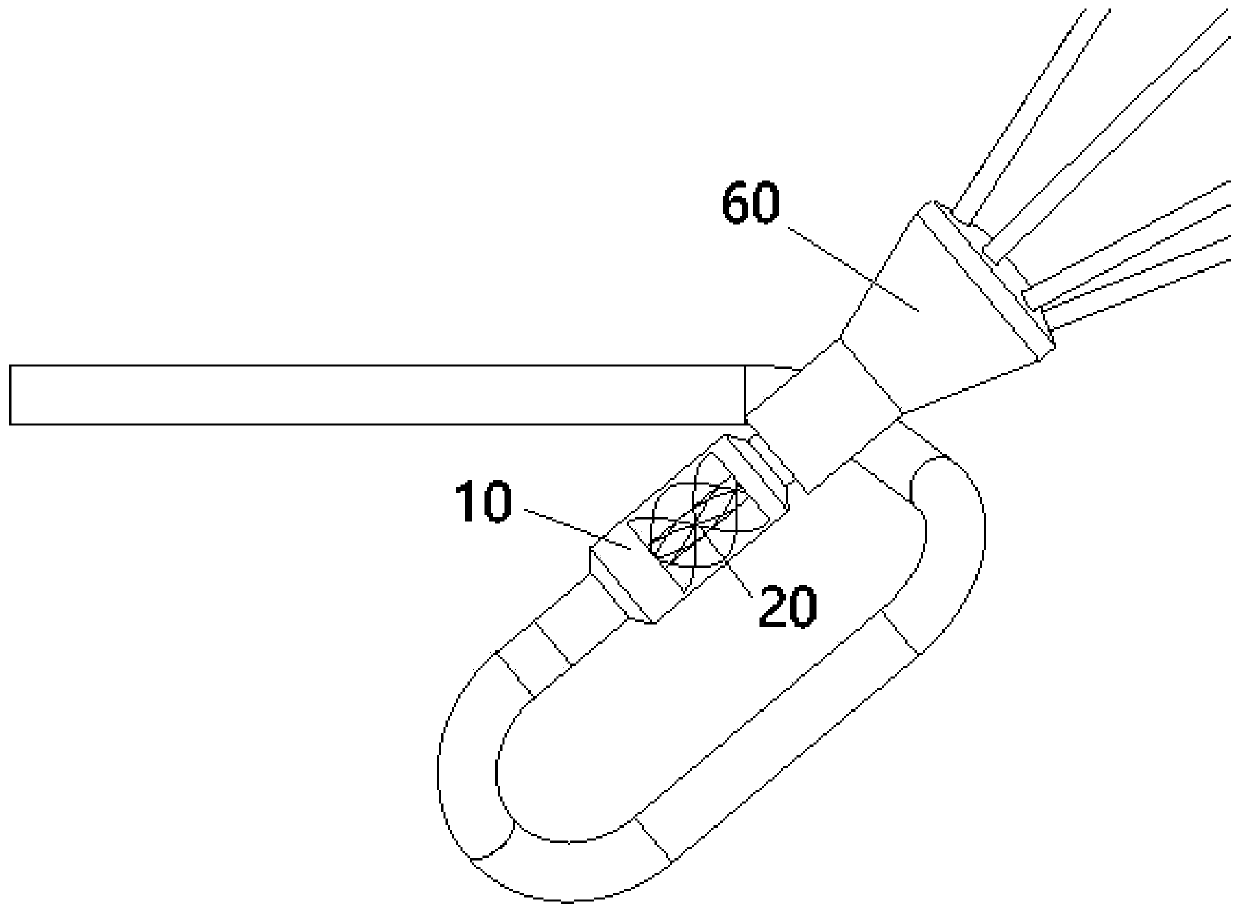
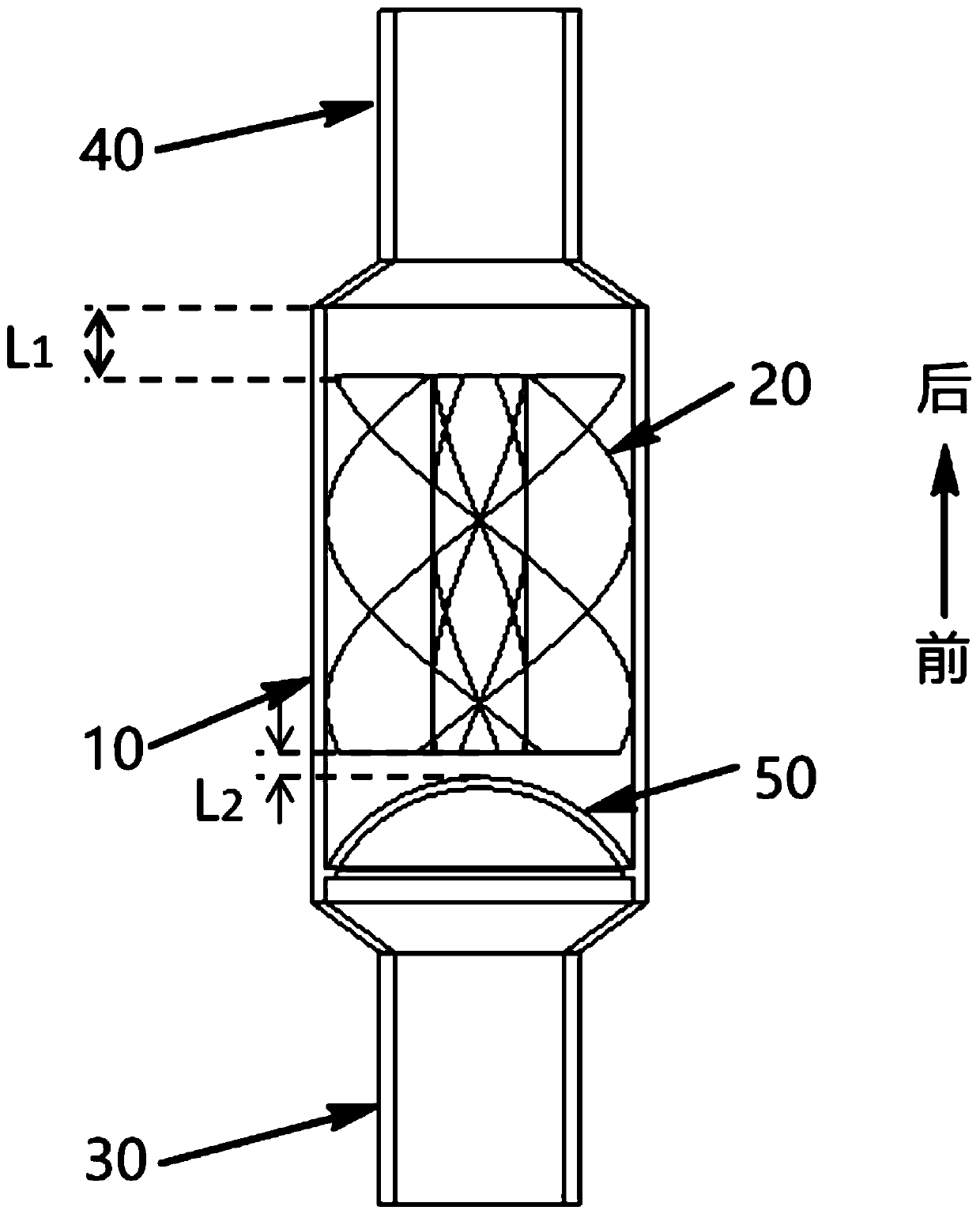
[0032] Such as figure 1 , figure 2 and Figure 8 As shown, the present invention provides an embodiment of a turbulence device, the turbulence device includes a pipe body 10 and a spiral turbulence body 20, the front end of the pipe body 10 is used for liquid inlet, and the rear end of the pipe body 10 is used for outlet The liquid is supplied to the splitter 60. The helical turbulence body 20 is fixedly arranged in the pipe body 10, and the helical turbulence body 20 is used to turbulence the fluid passing through the pipe body 10 so that the fluid is in an annular flow pattern.

[0033] ...


PUM


Abstract

The invention provides a turbulent flow device, a shunt assembly and an air conditioning unit. The turbulent flow device comprises a pipe body and a spiral turbulent flow body, the front end of the pipe body is used for feeding liquid, and the rear end of the pipe body is used for discharging liquid to a shunt. The spiral turbulent flow body is fixedly arranged in the pipe body and is used for conducting turbulent flow operation on the fluid passing through the pipe body to enable the fluid to be in an annular flow pattern. By adopting the technical scheme of the invention, before a refrigerant is led to the shunt, the refrigerant firstly passes through the flow disturbing device, enters the pipe body and then is subjected to turbulent flow operation under the action of the spiral flow disturbing body, so that the fluid is in the annular flow pattern, the gas-liquid two-phase states are symmetrically distributed along a circumferential direction, the favorable inlet conditions are provided for the shunt operation of the shunt, the shunt uniformity is improved, and an evaporator achieves the optimal heat exchange capacity.

Description

technical field [0001] The invention relates to the technical field of refrigeration equipment, in particular to a spoiler, a flow splitter assembly and an air conditioner unit. Background technique [0002] In order to ensure good heat exchange capacity of the evaporator, it is necessary to use a flow divider to increase the number of refrigerant flow paths. At the same time, after the refrigerant passes through the throttling element, the flash phase change is caused by the instantaneous pressure change, and the refrigerant in the diverter assembly is in a gas-liquid two-phase mixed state. [0003] As the two-phase refrigerant flows in the connecting pipe between the throttling element and the evaporator, the difference in flow velocity between the two phases and the continuous influence and drive of the force between the two phases, the gas-liquid two-phase state of the refrigerant presents a stratified flow at different cross-sections of the pipeline. Unstable and asymm...

Claims


Application Information

Patent Timeline
Patent Type & Authority Applications(China)
IPC IPC(8): F25B41/00F25B39/02F25B41/42
CPCF25B39/028F25B2500/09F25B41/40
Inventor 马屈杨夏凯玉格曾成林伟雪
Owner GREE ELECTRIC APPLIANCES INC
Why Eureka
Try Eureka