
Direct-current microgrid fault isolation method based on alternating-current circuit breaker removal

An AC circuit breaker and fault isolation technology, which is applied to emergency protection circuit devices and electrical components, can solve problems such as reduced reliability, potential safety hazards, and existence of relay protection, so as to improve reliability, reduce construction and operation costs, and improve Economical effect

Active Publication Date: 2019-12-03
TIANJIN UNIV
View PDF5 Cites 0 Cited by
  • Summary
  • Abstract
  • Description
  • Claims
  • Application Information

AI Technical Summary

Problems solved by technology

However, when the periodic minimum value of the fault current generated by the above method will be very large, even greater than the current during normal operation of the system, then the auxiliary arc extinguishing device and the AC circuit breaker will most likely fail, which will make the use of the method based on this method The reliability of the protection scheme of removing the AC circuit breaker is greatly reduced, and the system will have potential safety hazards in relay protection
[0005] Considering this, at the same time, the theoretical research and practical application of DC circuit breakers are not yet mature at this stage. Therefore, it is of great engineering significance to propose a transitional fault isolation scheme based on the high reliability of AC circuit breakers to remove fault lines. Urgent demand for microgrid system development and promotion

Method used


Image

  • Direct-current microgrid fault isolation method based on alternating-current circuit breaker removal
  • Direct-current microgrid fault isolation method based on alternating-current circuit breaker removal
  • Direct-current microgrid fault isolation method based on alternating-current circuit breaker removal

Examples


Embodiment Construction

[0024] The present invention will be described in further detail below in conjunction with accompanying drawing and example.

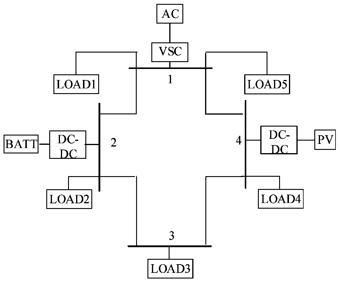
[0025] figure 1 Shown is a typical multi-terminal low-voltage DC micro-grid system. Compared with single-pole ground faults, the occurrence rate of inter-pole short-circuit faults is lower but the damage is the most serious. Therefore, the present invention only considers inter-pole short-circuits.

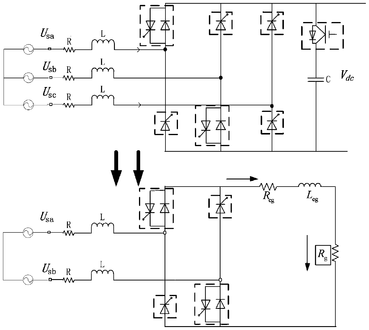
[0026] figure 2 This is the topology diagram of the VSC after a fault.

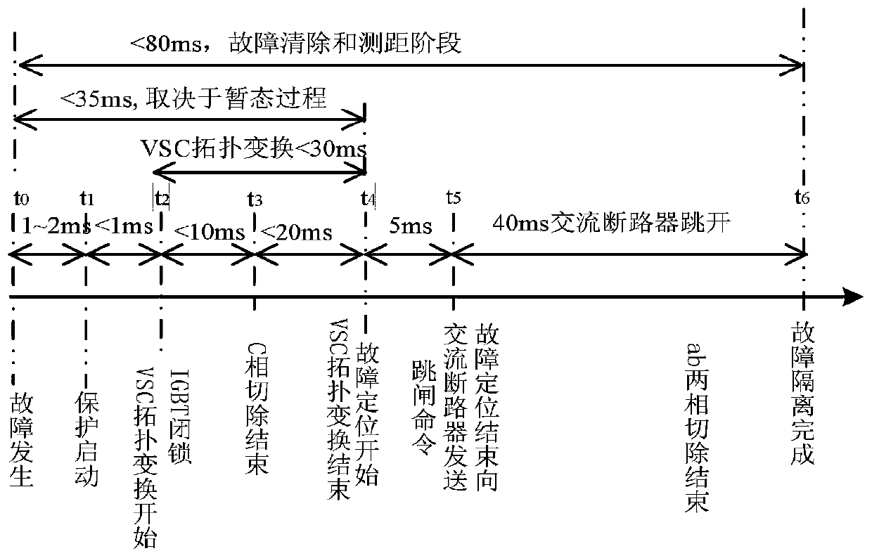
[0027] image 3 Sequence diagram of the action strategy for the fault isolation scheme. Figure 4 , 5 They are the simulation diagrams of DC side line fault current change in the case of metallic fault and 5 ohm transition resistance respectively (fault time is 0.5s). In order to compare and highlight the reliability of the AC circuit breaker action of this scheme, Figure 6 It is a simulation diagram of DC side fault current when there is a metallic fault (0.01 ohm) based on t...


PUM


Abstract

The invention relates to a direct-current microgrid fault isolation method based on alternating-current circuit breaker removal. The method comprises the following steps of: 1, alternating-current circuit breakers are installed at the two ends of a circuit, and topological transformation is conducted on a VSC at the same time as follows: in six bridge arms of three phases of the VSC, two thyristors are used for replacing antiparallel diodes in an upper bridge arm and a lower bridge arm of any one phase, the two thyristors are conducted all the time, and thyristor conduction signals at the positions are cancelled after protection is started, for the remaining four bridge arms of the two phases, in any group of upper and lower bridge arm branches belonging to the two different phases, a thyristor is used for replacing an antiparallel diode, the thyristors at the two positions are conducted all the time, and thyristor conduction signals at the positions are cancelled after protection is started, for the remaining two bridge arms which are not operated and belong to different two phases, the antiparallel diodes in the two bridge arms are respectively connected with the thyristors in parallel, the conduction forward direction is opposite to the direction of the corresponding antiparallel diode, and after the protection is started, the two thyristors are always conducted.

Description

technical field [0001] The invention belongs to the field of relay protection of electric power systems, and in particular relates to a DC micro-grid fault isolation scheme based on the removal of an AC circuit breaker. Background technique [0002] With the growth of social economy and the enhancement of human awareness of environmental protection, new energy has become a hot spot of widespread concern in the power and energy industry and has been widely promoted. In addition, the proportion of some DC loads such as electric vehicles, frequency conversion equipment, LED lighting, information equipment, etc. is increasing day by day. However, based on the voltage source converter (Voltage Source Converter, VSC) using pulse width modulation (PWM) to realize the DC microgrid mixed with the AC system, as the main grid, distributed power supply and DC load are higher The efficient access form has the advantages of high efficiency, large power supply capacity, good anti-interfer...

Claims


Application Information

Patent Timeline
Patent Type & Authority Applications(China)
IPC IPC(8): H02H7/26
CPCH02H7/268
Inventor 薛士敏武旭光刘存甲
Owner TIANJIN UNIV
Learn More