Permanent magnet auxiliary synchronous reluctance type motor rotor structure

A technology for assisting synchronous and motor rotors, applied in the direction of magnetic circuit shape/style/structure, magnetic circuit rotating parts, magnetic circuit, etc., can solve synchronous reluctance motor torque density, low efficiency and power factor, synchronous reluctance Problems such as poor mechanical performance and low speed of the motor, to achieve the effect of easy promotion and utilization, reasonable local settings, and increased utilization

Pending Publication Date: 2019-12-03
苏州英磁新能源科技有限公司
View PDF0 Cites 4 Cited by
  • Summary
  • Abstract
  • Description
  • Claims
  • Application Information

AI Technical Summary

Problems solved by technology

[0003] The torque density, efficiency and power factor of traditional synchronous reluctance motors are low, and because the synchronous reluctance motor rotor (generally referred to as TLA structure) adopts a multi-layer magnetic barrier structure, the magnetic bridge connection part bears a large centrifugal force , so the mechanical performance of the synchronous reluctance motor is poor, and it is generally used in a motor structure with a low speed and a stator outer diameter within 200mm

Method used


Image

  • Permanent magnet auxiliary synchronous reluctance type motor rotor structure
  • Permanent magnet auxiliary synchronous reluctance type motor rotor structure
  • Permanent magnet auxiliary synchronous reluctance type motor rotor structure

Examples


Embodiment Construction

[0030] The technical solutions of the present invention will be clearly and completely described below in conjunction with the accompanying drawings. Apparently, the described embodiments are some of the embodiments of the present invention, rather than all of them. Based on the embodiments of the present invention, all other embodiments obtained by persons of ordinary skill in the art without making creative efforts belong to the protection scope of the present invention.

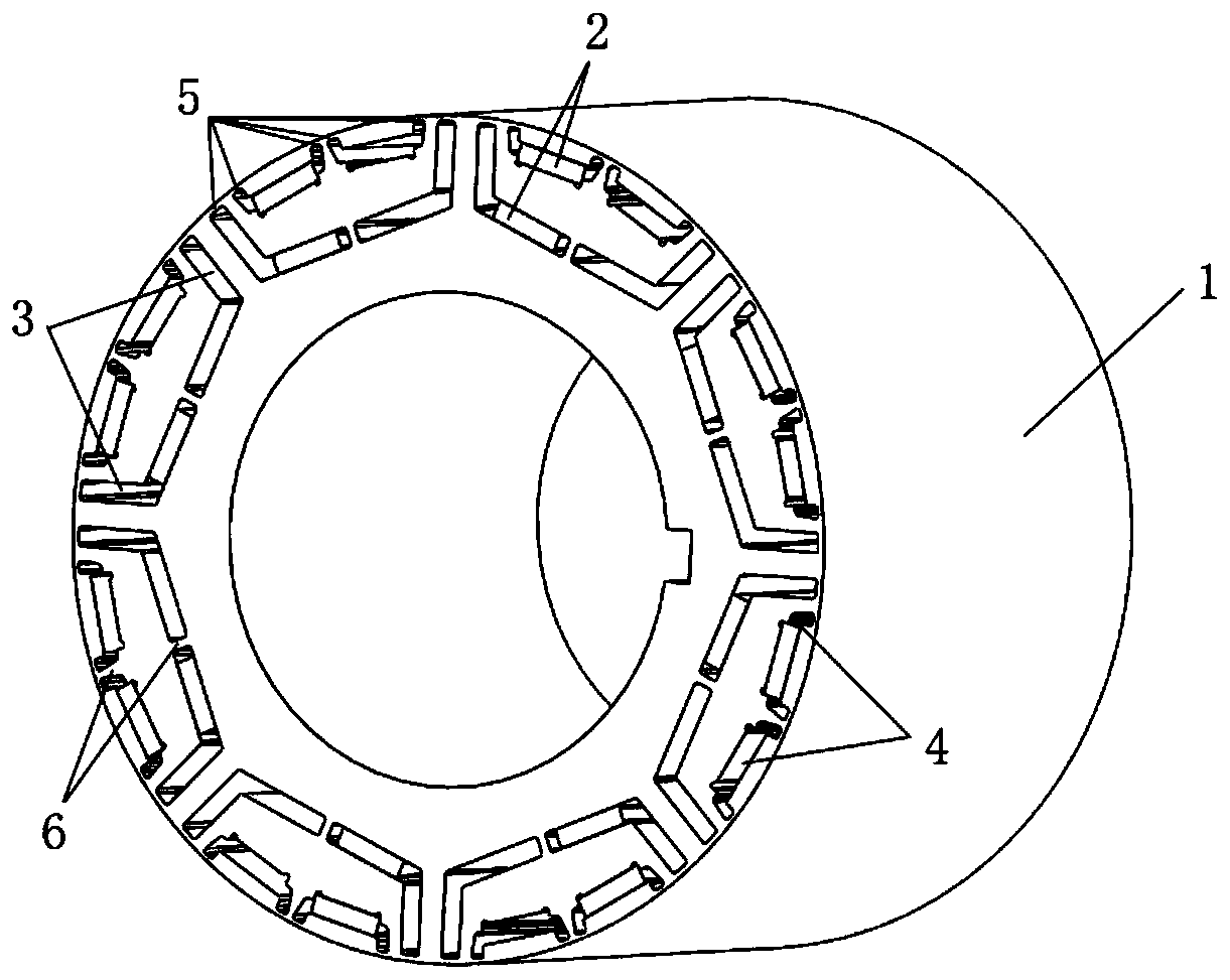
[0031] The present invention provides a permanent magnet assisted synchronous reluctance motor rotor structure, see for details figure 1 , including the rotor core, which differs from the prior art in that: the rotor core is provided with a number of U-shaped slots correspondingly arranged in the inner and outer layers; the number of U-shaped slots in the inner layer is 2P, and P is the pole pair of the rotor Each inner U-shaped groove is divided into two L-shaped grooves by reinforcing ribs; the number of...


PUM


Abstract

The invention relates to a permanent magnet auxiliary synchronous reluctance type motor rotor structure. A rotor core is provided with a plurality of U-shaped grooves, wherein the inner layer and theouter layer of each U-shaped groove are correspondingly arranged; each inner-layer U-shaped groove is divided into two L-shaped grooves through a reinforcing rib; every two outer-layer U-shaped grooves form a group and are arranged corresponding to one inner-layer U-shaped groove to form a magnetic space; and the inner U-shaped groove and the outer U-shaped groove are respectively provided with asecond permanent magnet and a first permanent magnet which are biased leftwards, so that the flux linkage of the rotor deviates, and the second permanent magnet of the inner U-shaped groove plays a role in magnetic conduction and corrects the deviation angle of the magnetic line of force passing through the first permanent magnet. The torque of the permanent magnet is improved, and the lengths andthe widths of the first permanent magnet and the second permanent magnet are the same, so that the utilization rate of the permanent magnets is increased, magnetic lines of force are gathered to theleft side, the offset of a rotor flux linkage is achieved, the reluctance torque is increased, and the material cost of the motor can be greatly reduced under the same torque requirement.

Description

technical field [0001] The present invention relates to the technical field of synchronous reluctance motors, in particular to a permanent magnet assisted synchronous reluctance motor rotor structure, in particular to a motor permanent magnet torque output by offsetting the permanent magnet flux linkage phase angle Electronic rotor structure. Background technique [0002] At present, synchronous reluctance motor has attracted attention in the field of AC speed regulation because of its low cost and good electromagnetic performance, but its torque density and efficiency are generally lower than those of permanent magnet synchronous motors of the same power level. Since the rotor of the synchronous reluctance motor has no excitation source, its excitation magnetic field comes from the stator armature current, and it works completely in an inductive state, so the power factor is smaller than that of the asynchronous motor and the permanent magnet synchronous motor. By insertin...

Claims


Application Information

Patent Timeline
Patent Type & Authority Applications(China)
IPC IPC(8): H02K1/27
CPCH02K1/27H02K1/2766H02K2213/03
Inventor 裴瑞琳郑杭兵徐佳伟
Owner 苏州英磁新能源科技有限公司
Why Eureka
Try Eureka