Power compensation method and device for radio frequency module, equipment and medium

A radio frequency module and power compensation technology, which is applied in the field of power compensation for radio frequency modules, can solve the problems of labor and time cost, and is not suitable for large-scale power testing and calibration, and achieve convenient operation and fast power testing and calibration. Effect

Active Publication Date: 2019-12-03
HANGZHOU BROADLINK ELECTRONICS TECH
View PDF7 Cites 8 Cited by
  • Summary
  • Abstract
  • Description
  • Claims
  • Application Information

AI Technical Summary

Problems solved by technology

However, for mass-produced RF modules, the above-mentioned power test method needs to connect each RF module to the instrume

Method used


Image

  • Power compensation method and device for radio frequency module, equipment and medium
  • Power compensation method and device for radio frequency module, equipment and medium
  • Power compensation method and device for radio frequency module, equipment and medium

Examples


Embodiment 1

[0031] This embodiment provides a power compensation method for the radio frequency module, aiming at simplifying the connection mode of the radio frequency module test without connecting the test instrument, so as to realize the fast power test and automatic power compensation of the radio frequency module, which is suitable for batch The test can improve the efficiency of batch testing, and has the advantages of convenient operation and low cost.

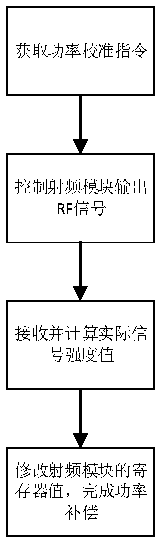
[0032] According to the above principles, the power compensation method for the RF module is introduced, such as figure 1 As shown, the power compensation method for the radio frequency module specifically includes the following steps:

[0033] Receive a power calibration command;

[0034] controlling the radio frequency module to output an RF signal according to the frequency offset calibration instruction;

[0035] The RF signal of the radio frequency module is received and converted into an actual signal strength value, and t...

Embodiment 2

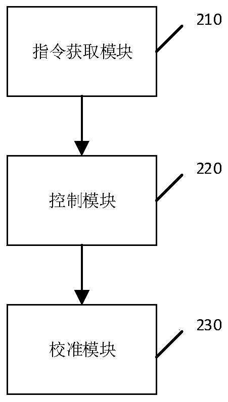
[0049] Embodiment 2 discloses a device corresponding to the power compensation method for the radio frequency module corresponding to Embodiment 1, please refer to figure 2 shown, including:

[0050] An instruction acquisition module 210, configured to acquire a power calibration instruction;

[0051] A control module 220, configured to control the radio frequency module to output an RF signal according to the frequency offset calibration instruction;

[0052] The calibration module 230 is configured to receive the RF signal of the radio frequency module, convert it into an actual signal strength value, and modify the register value based on the actual signal strength value.

Embodiment 3

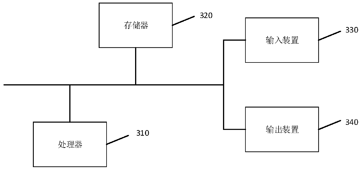
[0054] image 3 A schematic structural diagram of an electronic device provided by Embodiment 3 of the present invention, such as image 3 As shown, the electronic device includes a processor 310, a memory 320, an input device 330, and an output device 340; the number of processors 310 in a computer device may be one or more, image 3 Take a processor 310 as an example; the processor 310, memory 320, input device 330 and output device 340 in the electronic device can be connected by bus or other methods, image 3 Take connection via bus as an example.

[0055] The memory 320, as a computer-readable storage medium, can be used to store software programs, computer-executable programs and modules, such as program instructions / modules corresponding to the power compensation method for radio frequency modules in the embodiment of the present invention (for example, for radio frequency modules The command acquisition module 210, the control module 220, and the calibration module 2...


PUM


Abstract

The invention discloses a power compensation method for a radio frequency module, relates to the technical field of communication, aims to realize rapid power compensation for a wireless radio frequency module. The power compensation method can ensure the consistency of power calibration, is suitable for batch test, and comprises the following steps: receiving a power calibration instruction; controlling the radio frequency module to output an RF signal according to the power calibration instruction; and sampling the RF signal to calculate an actual signal strength value, and modifying a register value based on the actual signal strength value so as to complete power calibration. The invention further discloses a power compensation device for the radio frequency module, electronic equipment and a computer storage medium.

Description

technical field [0001] The present invention relates to the field of communication technologies, and in particular to a power compensation method, device, equipment and medium for a radio frequency module. Background technique [0002] In the process of R&D and marketization of wireless RF modules, according to the received signal strength indication, it is used to judge the quality of the communication link, so as to decide whether to increase the broadcast transmission strength. [0003] RF power is often used as an indicator for judging signal strength. At present, the industry mainly relies on some professional instruments to test RF power, such as Itest (wireless network tester) and spectrum tester. The professional instrument obtains a spectrum image by performing Fourier transform on the wireless signal, so as to realize the RF power test, and then perform power compensation based on the spectrum image. However, for mass-produced RF modules, using the above-mentioned...

Claims


Application Information

Patent Timeline
IPC IPC(8): H04B17/10H04B17/11H04B17/15H04B17/21H04B17/29
CPCH04B17/101H04B17/11H04B17/15H04B17/21H04B17/29
Inventor 王超军姚博刘宗孺李志为
Owner HANGZHOU BROADLINK ELECTRONICS TECH
Why Eureka
Try Eureka