
Tool head for a pressing device

A technology of tool heads and presses, which is applied in the plastic deformation of joints, tool heads of pipe presses, and presses, and can solve problems such as the difficulty in positioning the tool head accurately enough, the large size of the tool head, and the inability to ensure the sealing of the joint.

Active Publication Date: 2019-12-06
VON ARX AG
View PDF6 Cites 0 Cited by
  • Summary
  • Abstract
  • Description
  • Claims
  • Application Information

AI Technical Summary

Problems solved by technology

[0006] Furthermore, the known tool heads are bulky and can only be used to a limited extent in tight areas
In particular due to the relative pivoting of the pliers relative to one another, the surrounding volume of the known tool head changes very strongly when the pliers are opened, so that the known tool head is unsuitable or only limitedly suitable for use in confined areas ( e.g. when installing air conditioning or heating, especially when retrofitting air conditioning or heating modules)
[0007] Furthermore, the known tool heads are often difficult to position precisely enough so that the workpiece (joint) to be extruded is not ideally clamped prior to extruding
This can lead to deformations of the workpieces at locations that are not provided for deformations, so that the tightness of the joints of tubular workpieces cannot be ensured in the end.

Method used


Image

  • Tool head for a pressing device
  • Tool head for a pressing device
  • Tool head for a pressing device

Examples


Embodiment Construction

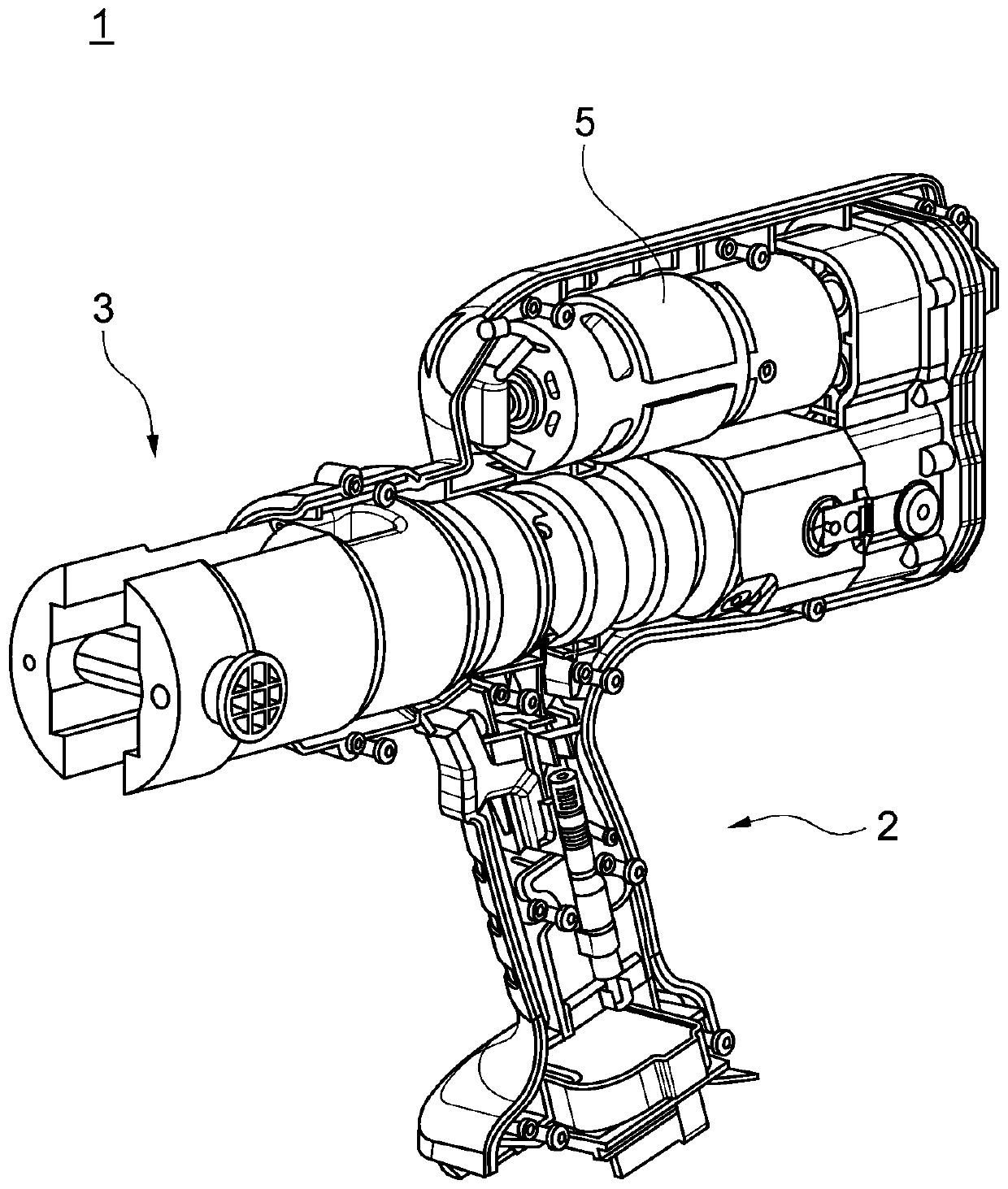
[0056] figure 1 A press 1 is shown in , which includes a handle 2 which can be manually guided by an operator or user. The tool bit 10 can be detachably coupled to the press 1 by means of the tool bit receptacle 3 .

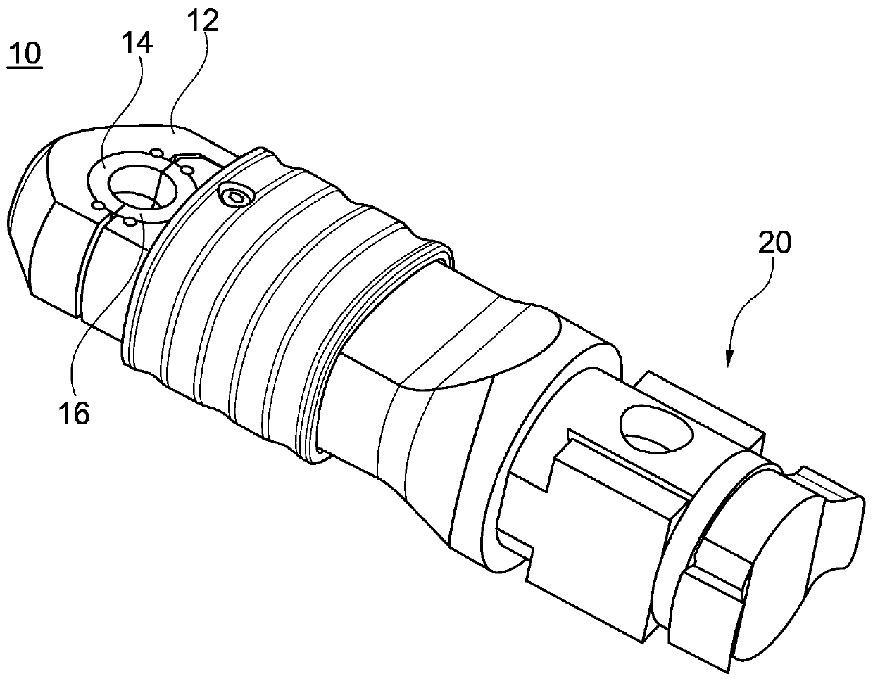
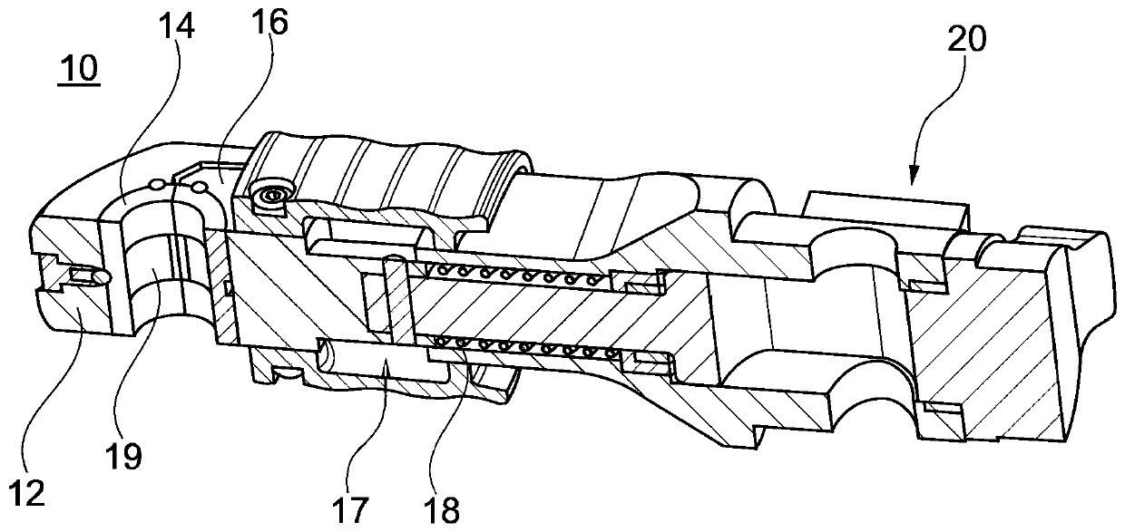
[0057] The press 1 also includes a drive 5 . The drive 5 can be an electric motor with a transmission, which drives the tool bit 10 via the tool bit receptacle 3 and thus can move the linearly movable press jaw 16 in order to plastically deform the workpiece. To deform the joint, the operator can actuate the corresponding joystick. By manipulating the joystick, the linearly movable pliers 16 of the tool head 10 first move from the stationary pliers 14 (see Figure 2A ) movement away. The workpiece or joint can then be clamped. The movable clamp 16 can then be pretensioned relative to the clamped joint, and by (re)actuating the joystick a force can be applied to the joint by means of the drive 5 via the clamp 14, 16 in order to plasticize the joint. out of s...


PUM

PropertyMeasurementUnit
diameteraaaaaaaaaa

Abstract

A tool head 10 for a pressing machine 1 and a pressing machine for plastically deforming a tubular workpiece, in particular a fitting, are described. The tool head includes a base body 12, a fixed press jaw 14 and a linearly movable press jaw 16. A spring element 18 is arranged to preload the movable press jaw against a workpiece without plastically deforming the workpiece.

Description

technical field [0001] The invention relates to a tool head for a press, in particular a tube press, for plastically deforming tube-shaped workpieces, in particular joints. Furthermore, the invention relates to a press and a method for operating such a press. Background technique [0002] Various methods are known in the prior art for connecting tubular workpieces. For example, the tubes can be welded or welded to one another. It is also known to insert the end of a smaller tube into the tube end of a larger tube and then press the two tube ends together. [0003] In other cases, extrusion is performed by means of (extrusion) joints. For this purpose, a press, for example a tube press, can be used to connect the tube with the extruded connection. Such a connection can be designed, for example, as a pipe connection, which can be used as a connection for pipes. The pipe ends to be connected are inserted into the fitting and the fitting is then pressed together with the pi...

Claims


Application Information

Patent Timeline
Patent Type & Authority Applications(China)
IPC IPC(8): B21D39/04
CPCB21D39/046B25B27/10B25B27/02B30B15/047
Inventor R·克鲁泽安德烈亚斯·斯塔基
Owner VON ARX AG
Learn More