Numerical control machining center-used convenient-to-use type device for clamping triangular workpieces

A workpiece clamp and triangular technology, which is applied to metal processing machine parts, positioning devices, metal processing equipment, etc., can solve the problems of affecting processing accuracy, unfavorable development and operation, and troublesome use, so as to improve processing accuracy, easy maintenance and repair, Ease of use

Active Publication Date: 2019-12-06
江苏春秋重型机械有限公司
View PDF7 Cites 2 Cited by
  • Summary
  • Abstract
  • Description
  • Claims
  • Application Information

AI Technical Summary

Problems solved by technology

[0002] Numerical control is the abbreviation of digital control. Numerical control technology is a method to control mechanical movement and processing process by using digital information. The numerical control machining center is a high-efficiency automatic machine tool composed of mechanical equipment and numerical control system suitable for processing complex parts. The comprehensive processing ability of the CNC machining center is strong, and

Method used


Image

  • Numerical control machining center-used convenient-to-use type device for clamping triangular workpieces
  • Numerical control machining center-used convenient-to-use type device for clamping triangular workpieces
  • Numerical control machining center-used convenient-to-use type device for clamping triangular workpieces

Examples


Example Embodiment

[0016] Example 1

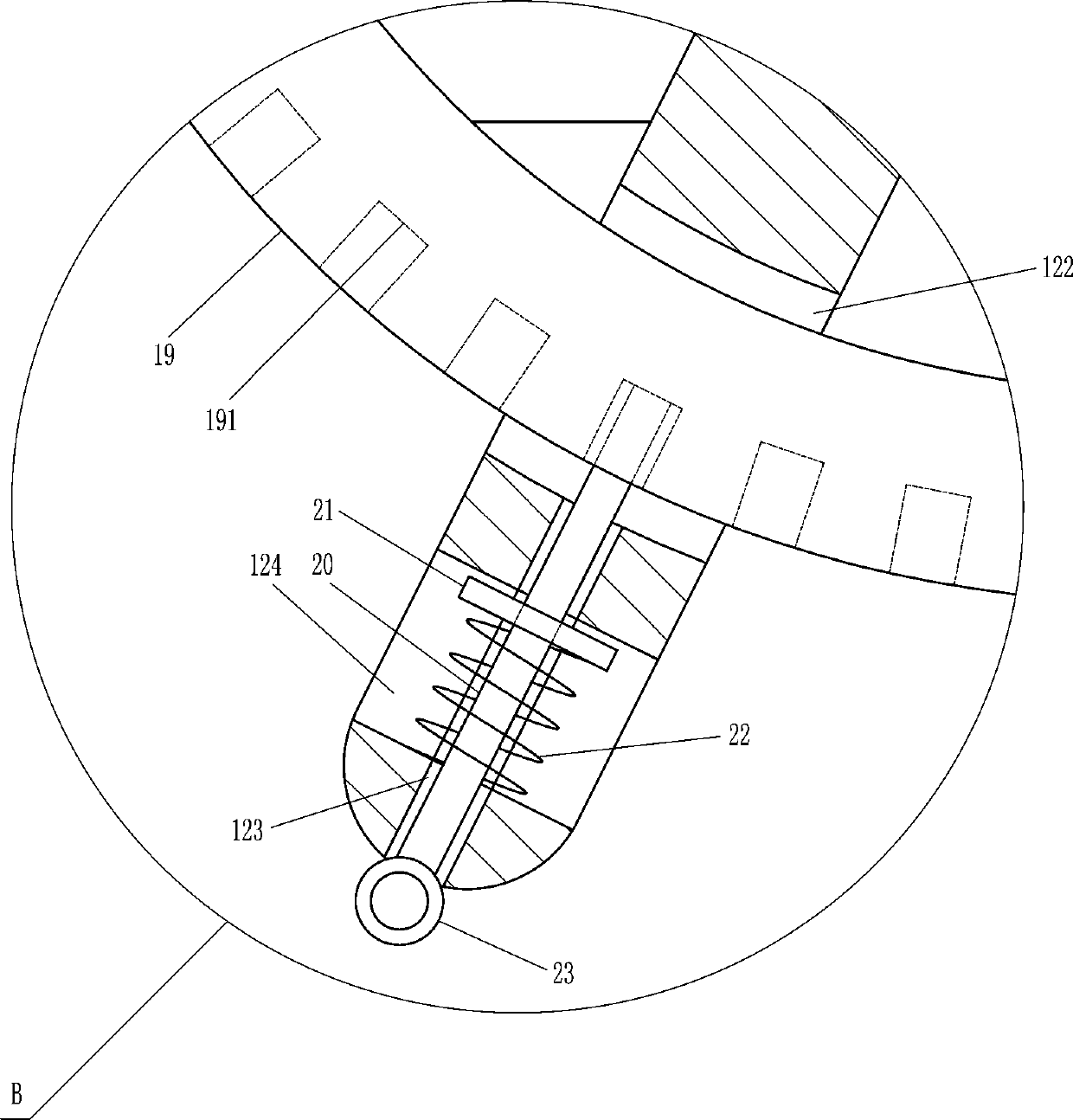
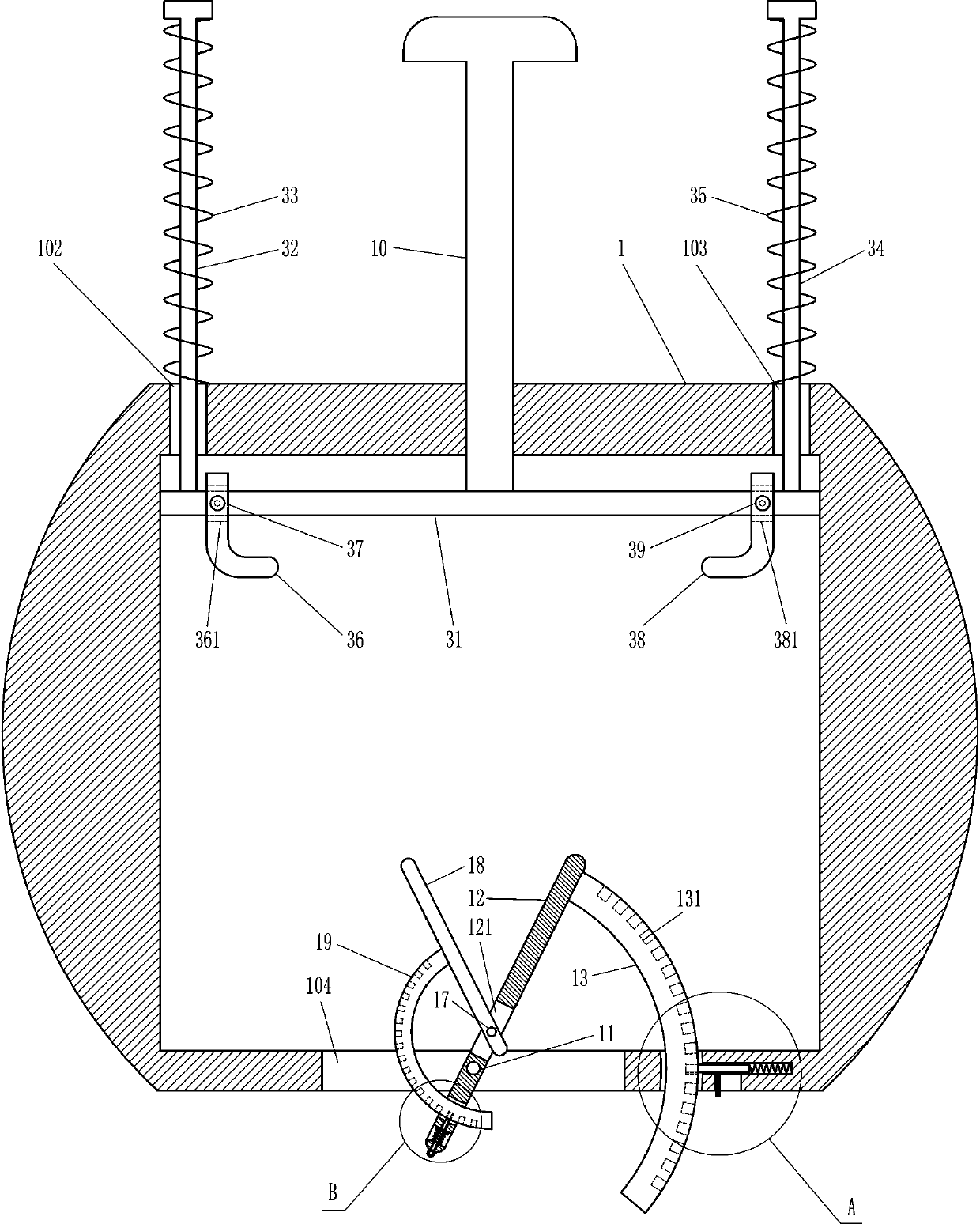
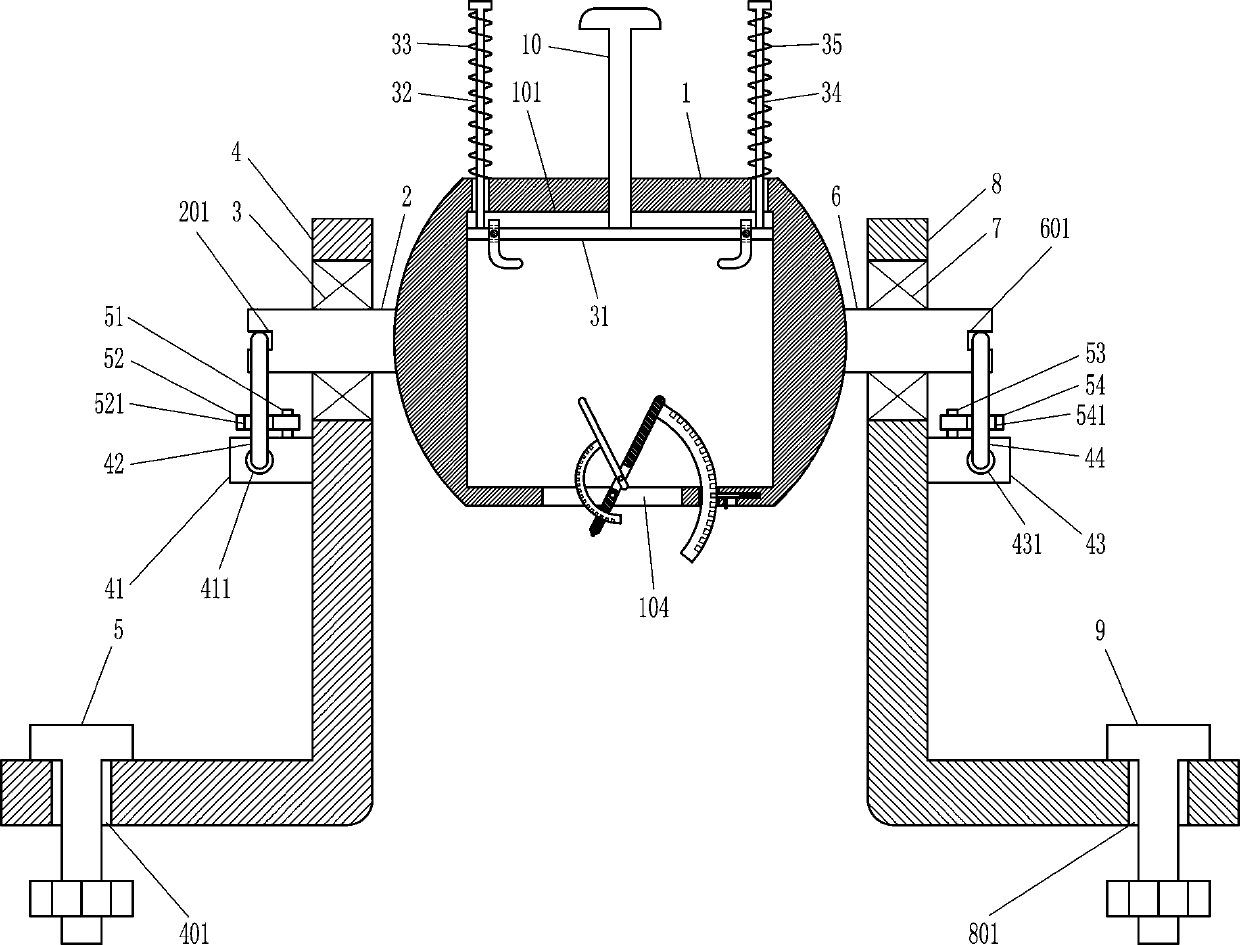
[0017] An easy-to-use triangular workholding device for CNC machining centers, such as Figure 1-4As shown, it includes a large movable plate 1, a first large rotating shaft 2, a first large bearing 3, a first large L-shaped plate 4, a first large bolt 5, a second large rotating shaft 6, a second large bearing 7, The second large L-shaped plate 8, the second large bolt 9, the large screw rod 10, the first rotating shaft 11, the large swing plate 12, the large arc guide plate 13, the large insertion rod 14, the large spring 15, the large shift lever 16, The second rotating shaft 17, the small swing plate 18, the small arc-shaped guide plate 19, the small insertion rod 20, the small baffle plate 21, the small spring 22 and the pull ring 23, the large movable plate 1 has a large rectangular groove 101 that runs through the front and back, The top of the large movable plate 1 has a first guide hole 102 and a second guide hole 103 extending downwards, the first ...

Example Embodiment

[0018] Example 2

[0019] An easy-to-use triangular workholding device for CNC machining centers, such as Figure 1-4 As shown, it includes a large movable plate 1, a first large rotating shaft 2, a first large bearing 3, a first large L-shaped plate 4, a first large bolt 5, a second large rotating shaft 6, a second large bearing 7, The second large L-shaped plate 8, the second large bolt 9, the large screw rod 10, the first rotating shaft 11, the large swing plate 12, the large arc guide plate 13, the large insertion rod 14, the large spring 15, the large shift lever 16, The second rotating shaft 17, the small swing plate 18, the small arc-shaped guide plate 19, the small insertion rod 20, the small baffle plate 21, the small spring 22 and the pull ring 23, the large movable plate 1 has a large rectangular groove 101 that runs through the front and back, The top of the large movable plate 1 has a first guide hole 102 and a second guide hole 103 extending downwards, the first...

Example Embodiment

[0021] Example 3

[0022] An easy-to-use triangular workholding device for CNC machining centers, such as Figure 1-5As shown, it includes a large movable plate 1, a first large rotating shaft 2, a first large bearing 3, a first large L-shaped plate 4, a first large bolt 5, a second large rotating shaft 6, a second large bearing 7, The second large L-shaped plate 8, the second large bolt 9, the large screw rod 10, the first rotating shaft 11, the large swing plate 12, the large arc guide plate 13, the large insertion rod 14, the large spring 15, the large shift lever 16, The second rotating shaft 17, the small swing plate 18, the small arc-shaped guide plate 19, the small insertion rod 20, the small baffle plate 21, the small spring 22 and the pull ring 23, the large movable plate 1 has a large rectangular groove 101 that runs through the front and back, The top of the large movable plate 1 has a first guide hole 102 and a second guide hole 103 extending downwards, the first ...


PUM


Abstract

The invention relates to a numerical control machining center-used clamping device, in particular to a numerical control machining center-used convenient-to-use type device for clamping triangular workpieces. According to the numerical control machining center-used convenient-to-use type device for clamping the triangular workpieces, the device can be adjusted; and improvement of the machining accuracy is benefited. According to the technical scheme, the numerical control machining center-used convenient-to-use type device for clamping the triangular workpieces comprises a big movable plate, afirst big rotary shaft, a first big bearing, a first big L-shaped plate, a first big bolt, a second big rotary shaft, a second big bearing and the like. A front-back-penetrating big rectangular groove is formed in the big movable plate. According to the provided numerical control machining center-used convenient-to-use type device for clamping the triangular workpieces, the structure is novel andunique; the triangular workpieces can be better clamped; the clamping effect is good; the use is convenient; improvement of the machining accuracy is benefited; carrying out and proceeding of work are benefited.

Description

technical field [0001] The invention relates to a clamping device for a numerical control machining center, in particular to an easy-to-use triangular workpiece clamping device for a numerical control machining center. Background technique [0002] Numerical control is the abbreviation of digital control. Numerical control technology is a method to control mechanical movement and processing process by using digital information. The numerical control machining center is a high-efficiency automatic machine tool composed of mechanical equipment and numerical control system suitable for processing complex parts. The CNC machining center has strong comprehensive processing ability and high machining accuracy, especially it can complete many processing that ordinary equipment cannot complete. After the workpiece is clamped by the fixture of the CNC machining center, the workpiece can be processed by the CNC machining center. Processing, the existing clamping device for CNC machini...

Claims


Application Information

Patent Timeline
IPC IPC(8): B23Q3/06
CPCB23Q3/062
Inventor 王建委
Owner 江苏春秋重型机械有限公司
Why Eureka
Try Eureka