Wind power generation blade device with ice removing capacity

A technology for wind power generation blades and ventilation devices, which is applied to wind turbines, wind energy power generation, wind turbines and other directions that are consistent with the wind direction, and can solve problems that are difficult to apply to large-sized, large pre-curved blades, turbine unit vibration power factor, unfavorable Promotion and popularization and other issues, to achieve the effect of reducing design risk, good versatility and adaptability, and wide applicability

Pending Publication Date: 2019-12-06
湖南天风科技有限公司
View PDF0 Cites 3 Cited by
  • Summary
  • Abstract
  • Description
  • Claims
  • Application Information

AI Technical Summary

Problems solved by technology

[0002] Wind turbines are usually installed in areas with high altitude, low temperature, high humidity, and frequent thunderstorms. Especially in winter, with the decrease of temperature and increase of humidity, the outer surface of wind turbine blades is very easy to freeze, and the ice on the blade surface will often Cause vibration or power factor distortion of the turbine unit and endanger the operation of the unit, so the unit must be shut down after freezing, causing a large amount of power loss to the wind farm
[0003] The deicing of the blades of the existing wind turbines is mainly realized by adding heating elements inside or outside the blades to heat the blades. Generally, there are technical routes such as gas heating and electric heating, and the structure of the conventional gas heating deicing system is difficult to apply Large size and large pre-curved blades have a small scope of application, which is not conducive to widespread promotion and popularization. Therefore, we provide a wind power generation blade device with deicing ability

Method used


Image

  • Wind power generation blade device with ice removing capacity
  • Wind power generation blade device with ice removing capacity
  • Wind power generation blade device with ice removing capacity

Examples


Embodiment 1

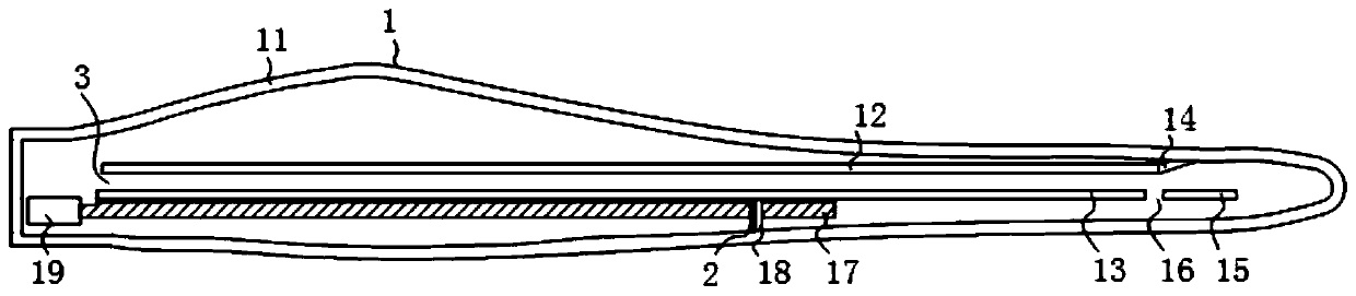
[0022] see figure 1 , a wind power generation blade device with deicing capability, comprising a wind power generation blade 1 and a leading edge air adjustment mechanism 2, the leading edge air adjustment mechanism 2 is installed in the wind power generation blade 1.

[0023] see figure 1 The wind power generation blade 1 includes a blade shell 11, a trailing edge web 12 is installed on the top of the inner wall of the blade shell 11, and a leading edge web 13 is installed on the inner wall of the blade shell 11 and below the trailing edge web 12, The blade web cavity 3 is formed between the trailing edge web 12 and the leading edge web 13, and the trailing edge windshield 14 is installed on the right side of the trailing edge web 12, and the trailing edge windshield 14 is close to the blade shell 11. One side is fixedly installed with the blade shell 11, and the trailing edge windshield 14 is mainly used to seal the cavity of the trailing edge of the blade, so that the hot ...

Embodiment 2

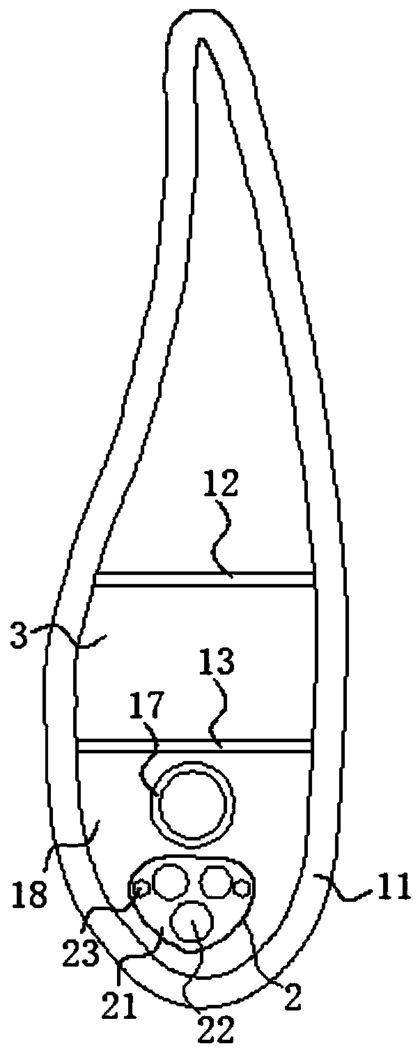
[0026] see image 3 , the front edge adjustment mechanism 2 includes the air hole adjustment pressure plate 21, the air hole adjustment pressure plate 21, the left side of the front edge windshield 18 and the position corresponding to the air hole adjustment pressure plate 21 is provided with a fixed ventilation hole 212 matching it, the wind The left side of the hole adjustment pressure plate 21 is provided with an adjustment bolt 213, and the rear end of the adjustment bolt 213 passes through the air hole adjustment pressure plate 21 and the front edge windshield 18 sequentially from left to right and extends to the inside of the front edge windshield 18 and its thread. Connection, by installing different adjusting bolts 213, the ventilation area of ​​the fixed ventilation hole 212 on the front edge windshield 18 can be adjusted, so as to realize flow and pressure regulation.

Embodiment 3

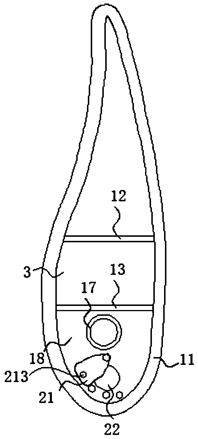
[0028] see Figure 4, the front edge adjustment mechanism 2 includes the air hole adjustment pressure plate 21, the air hole adjustment pressure plate 21, the left side of the front edge windshield 18 and the position corresponding to the air hole adjustment pressure plate 21 is provided with a fixed ventilation hole 212 matching it, the wind A cylinder 214 is installed on the top of the hole adjustment pressure plate 21, and the side of the cylinder 214 close to the front edge windshield 18 is fixedly installed with the front edge windshield 18. The cylinder 214 can drive the air hole adjustment pressure plate 21 to move up and down, thereby making the air hole adjustment The pressing plate 21 can regulate the area of ​​the fixed ventilation hole 212, and by adding a cylinder 214, the air regulating device can realize automatic air regulating.


PUM


Abstract

The invention discloses a wind power generation blade device with ice removing capacity. The device comprises a wind power generation blade and a front edge wind adjusting mechanism; the front edge wind adjusting mechanism is mounted in the wind power generation blade; the wind power generation blade comprises a blade shell; a back edge web is mounted at the top of the inner wall of the blade shell; a front edge web is mounted on the inner wall of the blade shell and positioned under the back edge web; and a back edge wind baffle plate is mounted on the right side of the back edge web. Throughcooperation of the back edge web, the front edge web, the back edge wind baffle plate, a front edge blade tip web, a blade tip ventilation hole, a ventilation pipe, a front edge wind baffle plate, aheating ventilation device, a wind hole adjusting pressure plate, an adjusting wind hole and a fixed bolt, the wind power generation blade device with the ice removing capacity is realized, the problem of incapability of directly arranging heating elements in a blade tip area of a wind power blade for heating and ice removal is solved, and the problems of higher wind pressure and higher flowing speed of a circulating system when a large-size and large-prebent blade adopts a traditional air heat circulating structure are solved.

Description

technical field [0001] The invention relates to the technical field of anti-icing and deicing technology for blades of wind power generating sets, in particular to a wind power generating blade device with deicing capability. Background technique [0002] Wind turbines are usually installed in areas with high altitude, low temperature, high humidity, and frequent thunderstorms. Especially in winter, with the decrease of temperature and increase of humidity, the outer surface of wind turbine blades is very easy to freeze, and the ice on the blade surface will often It causes vibration or power factor distortion of the turbine unit and endangers the operation of the unit. Therefore, the unit must be shut down after freezing, causing a large amount of power generation loss to the wind farm. [0003] The deicing of the blades of the existing wind turbines is mainly realized by adding heating elements inside or outside the blades to heat the blades. Generally, there are technical...

Claims


Application Information

Patent Timeline
IPC IPC(8): F03D80/40F03D80/60F03D1/06
CPCF03D1/0675F03D80/40F03D80/60Y02E10/72
Inventor 杨跃华杨文康
Owner 湖南天风科技有限公司
Why Eureka
Try Eureka