Electro-mechanical hydraulic line control brake
A brake-by-wire and electro-mechanical technology, applied in the direction of brake types, axial brakes, mechanical equipment, etc., can solve problems such as high space requirements, complex brake structure, and large installation size
Inactive Publication Date: 2019-12-06
ZHEJIANG NORMAL UNIVERSITY
View PDF9 Cites 4 Cited by
- Summary
- Abstract
- Description
- Claims
- Application Information
AI Technical Summary
Problems solved by technology
However, the existing electromechanical braking system often lacks the function of automatic adjustment of the brake gap in the brake part, which causes the problem that the efficiency of the brake actuator changes indeterminately when the external environment changes and the friction lining is worn. Braking efficiency control brings certain difficulties
At the same time, because the mechanical transmission parts need to achieve a large transmission ratio, they often have large dimensions and high space requirements, so most brakes have problems such as relatively complex structures and large installation dimensions.
Method used
View moreImage
Smart ImageViewing Examples

Examples
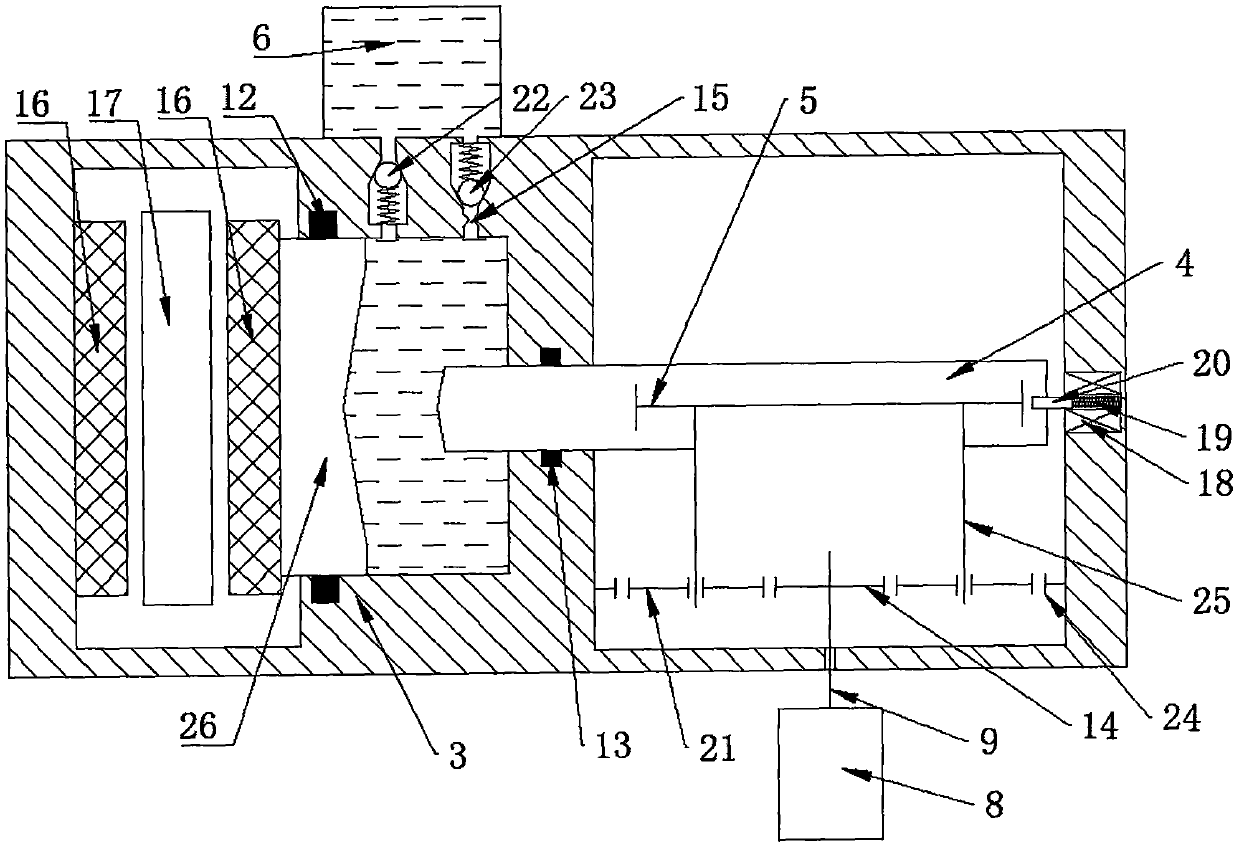
Embodiment 2
[0029] The working process of the second embodiment, the adjustment method of the braking clearance, etc. are basically the same as those of the first embodiment, and will not be described in detail here.
Login to View More PUM
 Abstract
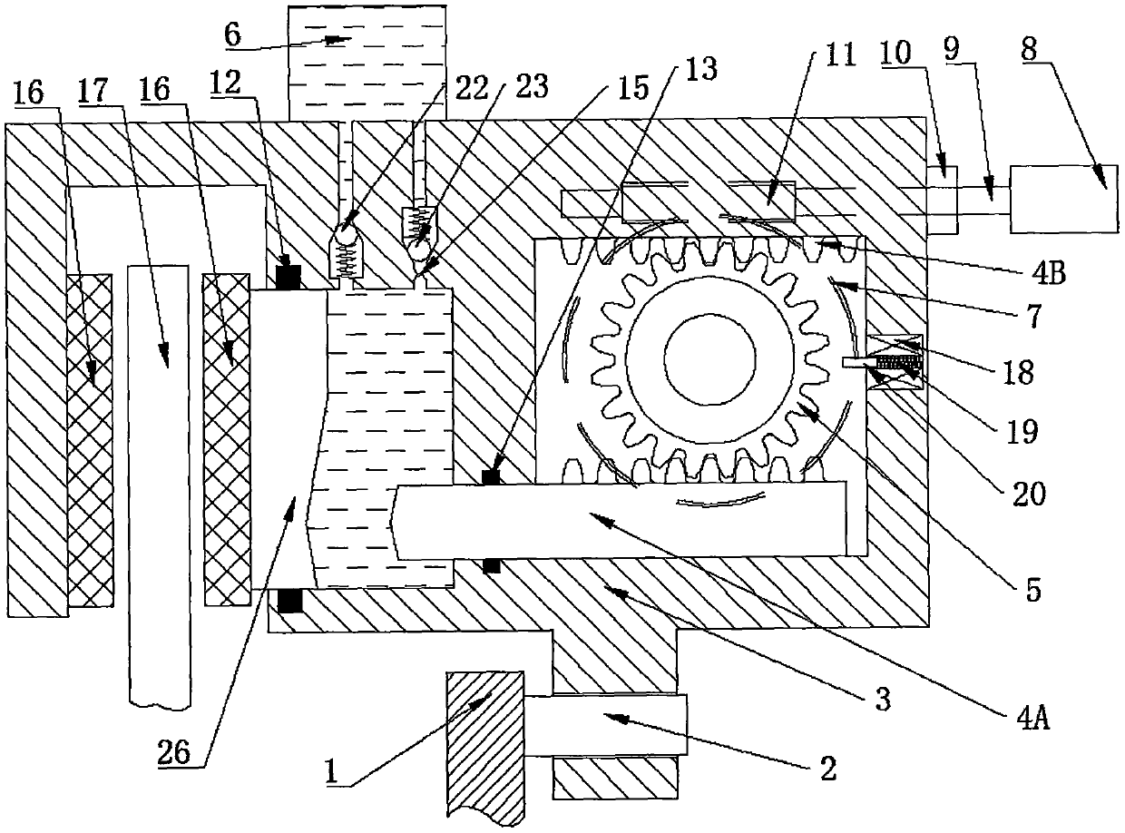
The invention relates to an electro-mechanical hydraulic line control brake which comprises a motor, a transmission mechanism, a gear, racks, a piston, a hydraulic system and other parts. The motor drives the gear to rotate through the transmission mechanism; a rack and pinion mechanism and the hydraulic system respectively drive the piston and a brake caliper body to move in opposite directions,and friction plates are pressed from two sides of a brake disc with the same force, thereby avoiding hydraulic system failure and possible effects caused by prolonged braking operation. The electro-mechanical hydraulic line control brake provided by the invention is simple in structure, reliable to work and high in braking efficiency, is capable of automatically adjusting the brake clearance, compensating for the influence caused by wear of the friction plates and simplifying the design of a control system, and can be used for service braking and parking braking.
Description
technical field [0001] The invention relates to the field of brakes, in particular, it can replace the existing floating caliper disc hydraulic brakes, realize friction plates clamping the brake discs from both sides with the same pressure in an electro-mechanical hydraulic manner, and at the same time realize adjustable brake clearances. Adjustable, brake-by-wire brake with adjustable braking strength, especially an electromechanical hydraulic brake-by-wire. Background technique [0002] Brake-by-wire technology is a new type of braking technology that has emerged in recent years. It does not rely on mechanical or hydraulic connections between the brake and the brake pedal. The control system receives the information from the sensor to control the motor to work. Stable and reliable brake control. At present, there are mainly two types of electronic hydraulic braking system (EHB) and electromechanical braking system (EMB). The brake-by-wire system is conducive to the optim...
Claims
Login to View More Application Information
Patent Timeline
 IPC IPC(8): F16D55/2265F16D65/14F16H63/34F16D123/00F16D121/04F16D121/24F16D125/06F16D125/08F16D125/16F16D125/24F16D125/52F16D127/06
CPCF16D55/2265F16D65/14F16D2121/04F16D2121/24F16D2123/00F16D2125/06F16D2125/08F16D2125/16F16D2125/24F16D2125/52F16D2127/06F16H63/345F16H63/3466F16H63/3475
Inventor 董颖常占辉
Owner ZHEJIANG NORMAL UNIVERSITY
Features
- R&D
- Intellectual Property
- Life Sciences
- Materials
- Tech Scout
- Unparalleled Data Quality
- Higher Quality Content
- 60% Fewer Hallucinations
Learn More Browse by: Latest US Patents, China's latest patents, Technical Efficacy Thesaurus, Application Domain, Technology Topic, Popular Technical Reports.
© 2025 PatSnap. All rights reserved.Legal|Privacy policy|Modern Slavery Act Transparency Statement|Sitemap|About US| Contact US: help@patsnap.com