Power box for photovoltaic equipment

A technology for photovoltaic equipment and power boxes, applied in the field of power boxes, can solve problems such as damage to power devices, small contact area, and few branches, and achieve the effects of increasing grounding area, increasing contact area, and ensuring stability

Active Publication Date: 2020-10-30
河北优优电气科技有限公司
View PDF6 Cites 0 Cited by
  • Summary
  • Abstract
  • Description
  • Claims
  • Application Information

AI Technical Summary

Problems solved by technology

[0002] Photovoltaic power generation is mainly composed of photovoltaic cell arrays, combiner boxes, low-voltage DC cabinets, inverter cabinets, AC low-voltage cabinets, and step-up transformers. When the high-voltage current flows through the combiner box, the combiner box is also a kind of power box. The ground terminal of the combiner box has a small contact area with the ground surface, and there are few branches. The current passing through a single circuit is excessive, and arc currents are prone to cause surrounding power Device damage, short circuit

Method used


Image

  • Power box for photovoltaic equipment
  • Power box for photovoltaic equipment
  • Power box for photovoltaic equipment

Examples


Embodiment

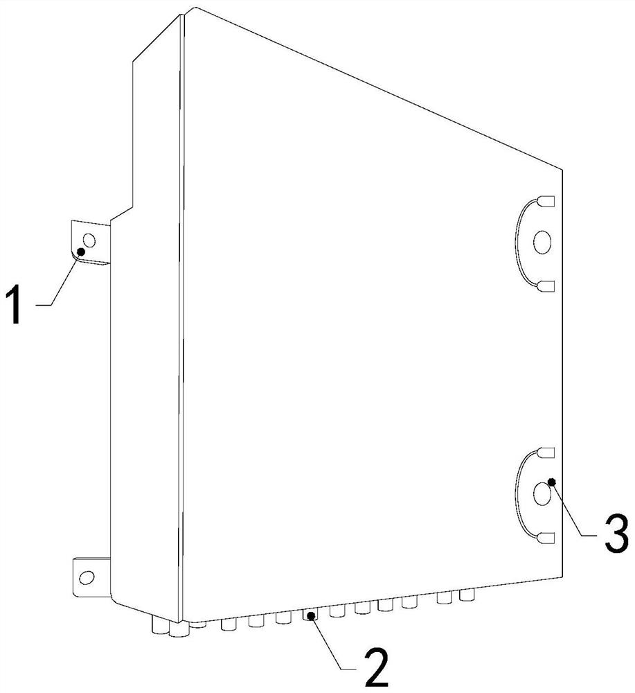
[0025] see Figure 1-Figure 5 , the present invention provides a power box for photovoltaic equipment, the structure of which includes a fixed plate 1, a ground terminal 2, a box body 3, a circuit breaker, a transformer, and an inverter, and the box body 3 is equipped with a circuit breaker, a transformer, and an inverter The ground terminal 2 is installed at the bottom of the box body 3, and the upper and lower ends of the side of the box body 3 are respectively horizontally fixed with fixed pieces 1.

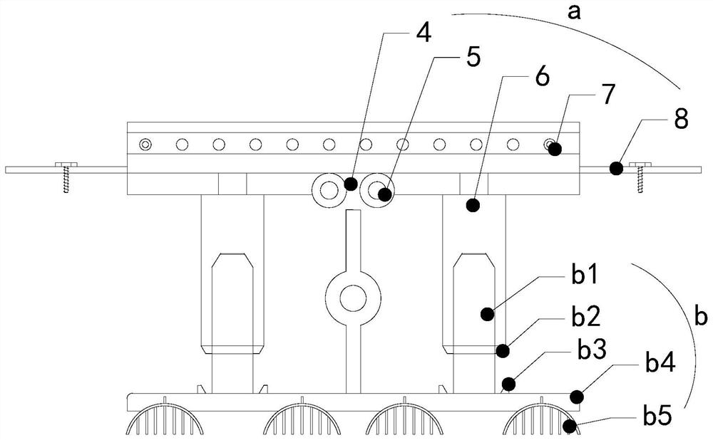
[0026] The ground terminal 2 is composed of an electrical connection structure a and a parallel conductive structure b. The electrical connection structure a is installed at the bottom of the box body 3. The bottom structure of the electrical connection structure a runs through the bottom of the box body 3 and is mechanically connected to the parallel conductive structure b. , the parallel conductive structure b is located outside the box body 3 .

[0027] The electrical conn...


PUM


Abstract

The invention discloses a power box for photovoltaic equipment. The power box structurally comprises fixing pieces, a grounding terminal, a box body, a circuit breaker, a transformer, an inverter andthe like; a circuit breaker, a transformer and an inverter are installed in the box body; the bottom of the box body is provided with a grounding terminal; the fixing pieces are horizontally fixed tothe upper and lower ends of the side face of the box; the grounding terminal is composed of a power connection structure and a parallel conductive structure; the power connection structure is mountedat the bottom end in the box body; the bottom structure of the power connection structure penetrates through the bottom of the box body and is mechanically connected with the parallel conductive structure; the parallel conductive structure is located outside the box body; the grounding area of the whole grounding terminal is increased through the aluminum plate of the parallel conductive structure, and a current generated by thunder and lightning is rapidly guided into the ground, thereby avoiding the current overload of the grounding terminal. According to the invention, the connection relation between a power connection column and a conductive column is increased through a clamping ring and a sleeve ring, and the stability of current conduction is guaranteed.

Description

technical field [0001] The invention relates to the field of electric boxes, in particular to an electric box for photovoltaic equipment. Background technique [0002] Photovoltaic power generation is mainly composed of photovoltaic cell arrays, combiner boxes, low-voltage DC cabinets, inverter cabinets, AC low-voltage cabinets, and step-up transformers. When the high-voltage current flows through the combiner box, the combiner box is also a kind of power box. The ground terminal of the combiner box has a small contact area with the ground surface, and there are few branches. The current passing through a single circuit is too much, and arc currents are prone to occur and cause surrounding power. Device damage, short circuit. Contents of the invention [0003] Aiming at the deficiencies of the prior art, the present invention is realized through the following technical solutions: a power box for photovoltaic equipment, the structure of which includes a fixed piece, a grou...

Claims


Application Information

Patent Timeline
Patent Type & Authority Patents(China)
IPC IPC(8): H02B1/46H02B1/16H01R4/66
CPCH01R4/66H02B1/16H02B1/46
Inventor 刘景娟
Owner 河北优优电气科技有限公司
Why Eureka
Try Eureka