
X-ray imaging device

A camera device, X-ray technology, applied in image analysis, image enhancement, image data processing and other directions, can solve the problem of intervertebral deformation and unable to detect the intervertebral, achieve the effect of reducing the workload of the work

Active Publication Date: 2019-12-06
SHIMADZU SEISAKUSHO CO LTD
View PDF10 Cites 0 Cited by
  • Summary
  • Abstract
  • Description
  • Claims
  • Application Information

AI Technical Summary

Problems solved by technology

However, there is a disadvantage that the intervertebral cannot be detected, such as the case where there is intervertebral deformation

Method used


Image

  • X-ray imaging device
  • X-ray imaging device
  • X-ray imaging device

Examples


Embodiment Construction

[0030] Hereinafter, embodiments embodying the present invention will be described based on the drawings.

[0031] refer to Figure 1 to Figure 6 The configuration of the X-ray imaging apparatus 100 according to one embodiment will be described.

[0032] (Structure of X-ray imaging device)

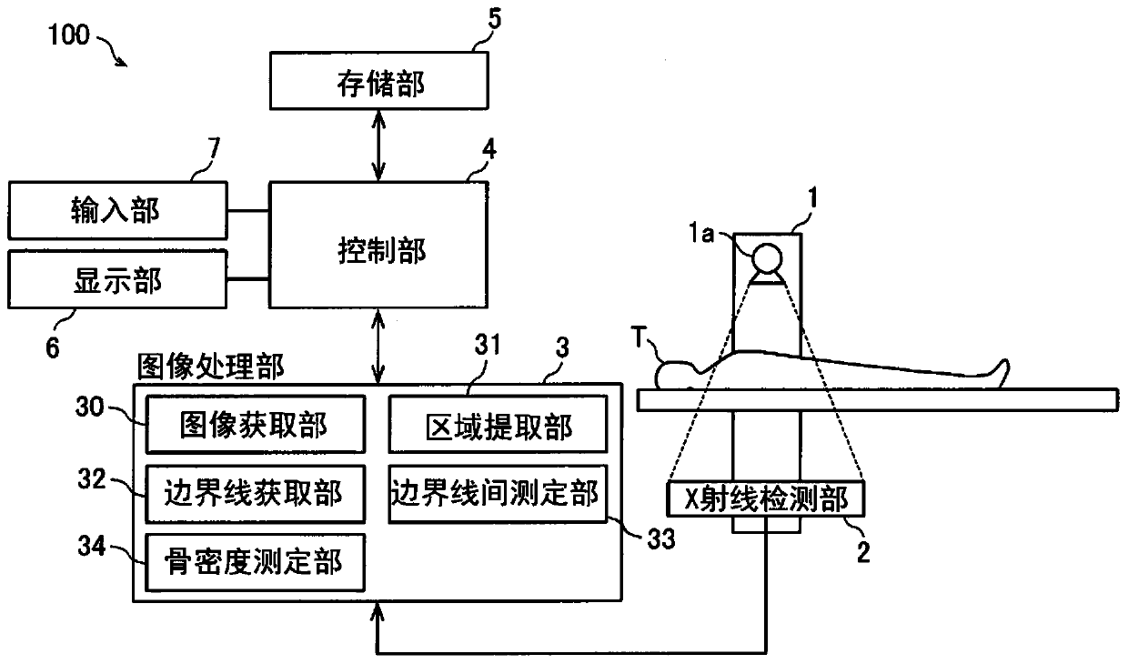
[0033] Such as figure 1 As shown, the X-ray imaging device 100 includes an X-ray irradiation unit 1 , an X-ray detection unit 2 , an image processing unit 3 , a control unit 4 , and a storage unit 5 .

[0034] The X-ray irradiation unit 1 irradiates the subject T with X-rays. The X-ray detection unit 2 detects the X-rays irradiated to the subject T from the X-ray irradiation unit 1 . The X-ray imaging device 100 is used to measure the bone density of the subject T, for example. In the measurement of bone density, for example, DEXA (Dual-Energy X-ray Absorptiometry: Dual-Energy X-ray Absorptiometry: Dual-Energy X-ray Absorptiometry: Dual-Energy X-ray Absorptiometry: Dual-Energy X-ray A...


PUM


Abstract

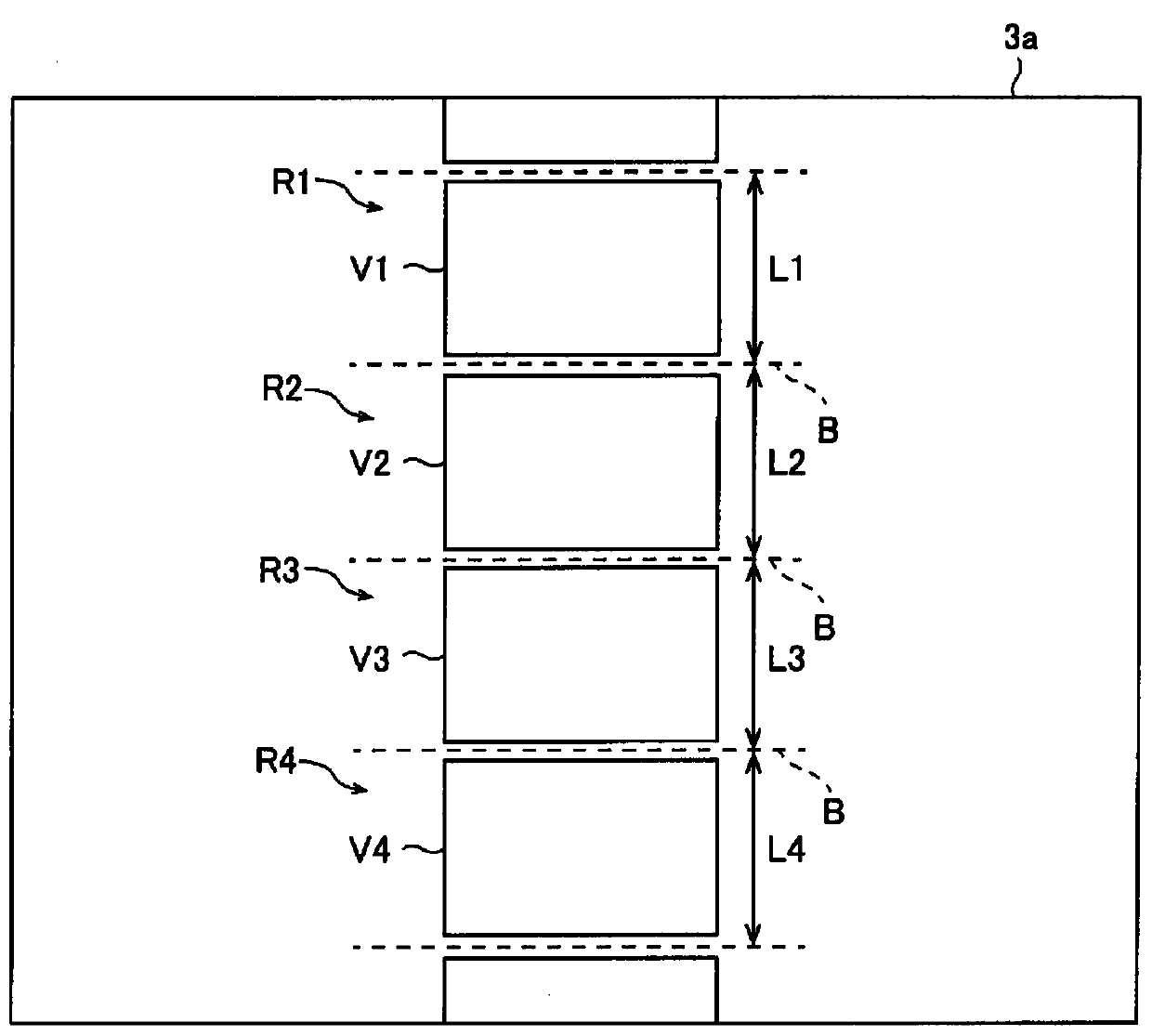
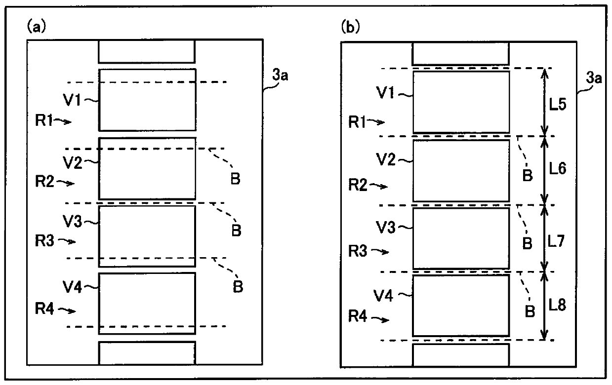
An X-ray imaging device (100) includes: an image processing unit (3) which, within limited ranges (L1 to L4) of lengths of a plurality of regions (R1 to R4) of a subject (T), extracts each of the regions (R1 to R4); and a control unit (4) that controls the limited ranges (L1 to L4) so as to reflect the results of corrections made by a user on the boundaries between the regions (R1 to R4) extractedby the image processing unit (3) if such corrections have been made.

Description

technical field [0001] The present invention relates to an X-ray imaging device, and more particularly to an X-ray imaging device for extracting a predetermined region in an image of a subject. Background technique [0002] Conventionally, there is known an X-ray imaging device that extracts a predetermined region from an image of a subject. Such an X-ray imaging device is disclosed in, for example, International Publication No. 2015 / 025387. [0003] Conventionally, in a bone densitometry device or the like, the region of the vertebral body of the subject is automatically extracted from the captured image of the subject. In this conventional bone densitometry device, for example, the region of each vertebral body is automatically extracted by detecting the boundary line between adjacent vertebral bodies. In addition, the boundary line between the vertebral bodies is detected based on the fact that the pixel value between the vertebral bodies is low in the image of the subj...

Claims


Application Information

Patent Timeline
Patent Type & Authority Applications(China)
IPC IPC(8): A61B6/00
CPCA61B6/00A61B6/5217A61B6/5205A61B6/505A61B6/469G06T7/11G06T2207/10116
Inventor 中矢知宏能登原大介
Owner SHIMADZU SEISAKUSHO CO LTD
Learn More