
Humerus locator and humerus positioning system

A locator and humerus technology, applied in the direction of surgical instruments, applications, etc., can solve the problems of occupying large tuberosity bone volume, high economic cost, unfavorable secondary revision, etc., to achieve convenient surgery, multiple options, and reduce trauma Effect

Active Publication Date: 2020-06-23
马佳
View PDF4 Cites 0 Cited by
  • Summary
  • Abstract
  • Description
  • Claims
  • Application Information

AI Technical Summary

Problems solved by technology

The suture method with threaded anchor, in addition to the economic cost is higher than that of perforating suture suture, there is also the risk of anchor pulling out, occupying the large tuberosity of bone, tendon slipping at the anchor suture point, and is not conducive to secondary revision, etc. Disadvantages that technology itself cannot overcome

Method used


Image

  • Humerus locator and humerus positioning system
  • Humerus locator and humerus positioning system
  • Humerus locator and humerus positioning system

Examples


Embodiment Construction

[0015] Example embodiments will now be described more fully with reference to the accompanying drawings. Example embodiments may, however, be embodied in many forms and should not be construed as limited to the embodiments set forth herein; rather, these embodiments are provided so that this disclosure will be thorough and complete, and will fully convey the concept of example embodiments to those skilled in the art. In the drawings, the thicknesses of regions and layers may be exaggerated for clarity. The same reference numerals in the drawings denote the same or similar structures, and thus their detailed descriptions will be omitted.

[0016] Furthermore, the described features, structures, or characteristics may be combined in any suitable manner in one or more embodiments. In the following description, numerous specific details are provided in order to give a thorough understanding of embodiments of the invention. However, one skilled in the art will appreciate that th...


PUM


Abstract

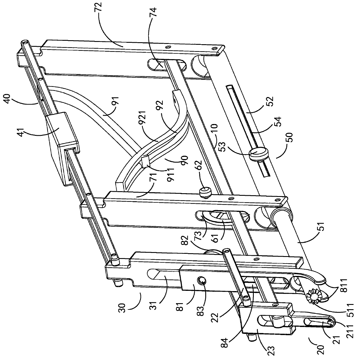
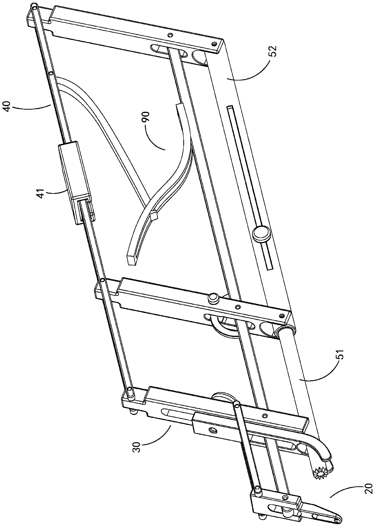
The invention relates to a humerus positioning machine and a humerus positioning system. The humerus positioning machine comprises a main rod, a front end structure, a positioning structure, a grasping and holding rod, a swinging rod structure and a guiding structure, wherein the front end structure is in pivoting connection with the front end of the main rod; a through hole is formed in the frontend structure; the positioning structure is in pivoting connection with the main rod and the front end structure, and the positioning structure and the front end structure are arranged side by side;the grasping and holding rod is in pivoting connection with the positioning structure; the swinging rod structure is in pivoting connection with the main rod and the grasping and holding rod; the guiding structure is in pivoting connection with the swinging rod structure; the guiding structure is hollow; one end of the guiding structure is adjacent to the through hole; and the guiding structure isaligned to the center of the through hole. According to the humerus positioning machine disclosed by the invention, the main rod, the front end structure, the positioning structure, the grasping andholding rod and the swinging rod structure are arranged to form a polygonal framework; and the grasping and holding rod is pushed, so that the front end structure, the positioning structure and the swinging rod structure can be driven to rotate relative to the main rod, the inclined angle between the front end structure and the main rod, the inclined angle between the positioning structure and themain rod and the inclined angle between the swinging rod structure and the main rod are adjusted, and the humerus positioning machine can move between an initial state and an extruding state.

Description

technical field [0001] The invention relates to a scheme for arthroscopic treatment of rotator cuff tear, in particular to a humerus locator with preset sutures in the rotator cuff suture method of minimally invasive subosseous sutures. Background technique [0002] Against the backdrop of the gradual increase in the proportion of the elderly population in my country, rotator cuff injuries are a common geriatric disease. Foreign literature has reported that more than 50% of the elderly over 60 years old have partial-thickness or full-thickness tears of the rotator cuff. . Although asymptomatic rotator cuff tears do not require surgical treatment, patients with symptoms that cannot be relieved by conservative treatment still need rotator cuff suture repair surgery to solve the problem. At present, most of the rotator cuff repairs are sutured with threaded anchors in China. As more clinicians gradually understand rotator cuff injuries, the number of operations is gradually inc...

Claims


Application Information

Patent Timeline
Patent Type & Authority Patents(China)
IPC IPC(8): A61B17/04
CPCA61B17/0469A61B17/0491
Inventor 马佳张磊崔国庆敖英芳刘晓华冯敏山朱立国
Owner 马佳
Learn More