Device for correcting pre-tightening force between firing pin and nozzle and piezoelectric injection valve thereof

A piezoelectric spraying and preloading force technology, which is applied to the device and coating of the surface coating liquid, which can solve the problems of affecting the dispensing accuracy, easy deviation of the preloading force, and difficult to grasp the nozzle installation position. , to achieve the effect of improving maintenance efficiency and reducing assembly difficulty

Pending Publication Date: 2019-12-10
CHANGZHOU GAO KAI PRECISION MACHINERY CO LTD
0 Cites 13 Cited by

AI-Extracted Technical Summary

Problems solved by technology

[0005] The technical problem to be solved by the present invention is: in order to solve the problem that in the prior art, when the nozzle is reinstalled on the piezoelectric injection valve, it is difficult to grasp the installation position of the nozzle, which leads to the deviation of the pre-tig...

Method used

There are two clamping arms 1-2 on the valve body 1, and the adjusting lever 11 is positioned between the two clamping arms 1-2, and the side of the adjusting lever 11 is provided with a locking screw 15, so The locking screw 15 is connected between the two clamping arms 1-2; the two clamping arms 1-2 are used to clamp the adjusting rod 11 by using the locking screw 15, so that the adjusting rod 11 can be prevented from loosening; specifically, this In the embodiment, the threaded end of the locking screw 15 can pass through one clamp arm 1-2 and be threadedly connected with the other clamp arm 1-2; it can also be that the threaded end of the locking screw 15 passes through the two clamping arms at the same time 1-2, and screw the nut on the locking screw 15, and use the nut and the nut of the locking screw 15 to clamp the two clamping arms 1-2.
When changing the no...

Abstract

The invention relates to the technical field of piezoelectric injection valves, in particular to a device for correcting pre-tightening force between a firing pin and a nozzle. The device comprises afirst adjusting mechanism and a second adjusting mechanism, wherein the first adjusting mechanism is provided with a pre-tightening piece and an upper adjusting block and a lower adjusting block whichare matched with each other; and the second adjusting mechanism is provided with an adjusting rod, and the bottom end of the adjusting rod abuts against the upper surface of the upper adjusting block. According to the device, the first adjusting mechanism is ingeniously utilized to roughly adjust the horizontal position of a lever so as to facilitate assembly of a piezoelectric actuator, the position of the lever is accurately adjusted in a follow-up manner by matching with the second adjusting mechanism, so that the pre-tightening force between the firing pin and the nozzle is adjusted, andthe problem that the piezoelectric actuator is too loose or too tight during adjustment can be avoided; and the nozzle at the current installation position can be adapted by driving the firing pin tomove after being mounted in the nozzle, the mounting position of the nozzle does not need to be accurately mastered, the assembly difficulty of the nozzle is greatly reduced, and the maintenance efficiency of the nozzle is improved.

Application Domain

Liquid surface applicatorsCoatings

Technology Topic

Piezoelectric actuatorsNozzle

Image

  • Device for correcting pre-tightening force between firing pin and nozzle and piezoelectric injection valve thereof
  • Device for correcting pre-tightening force between firing pin and nozzle and piezoelectric injection valve thereof

Examples

  • Experimental program(2)

Example Embodiment

[0027] Example 1
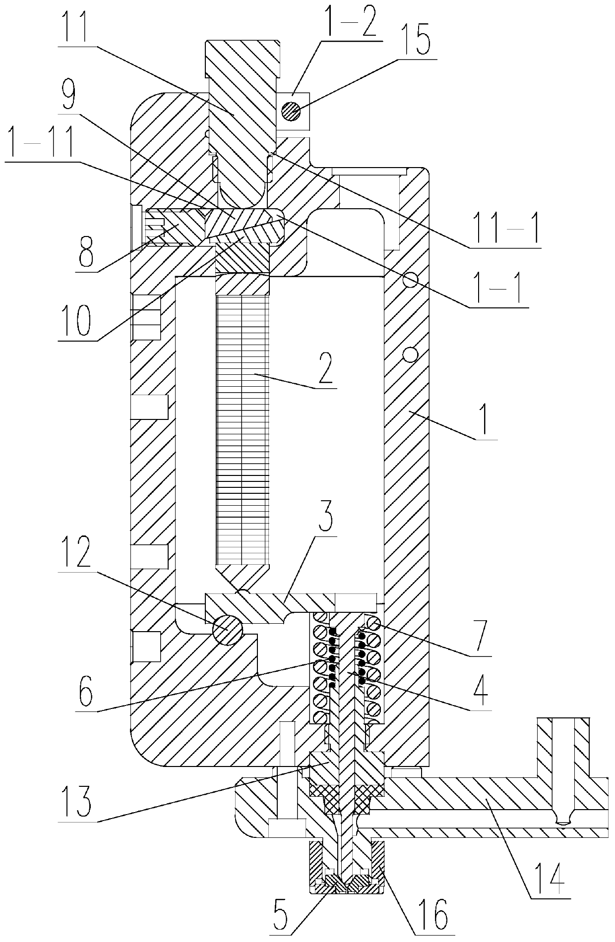
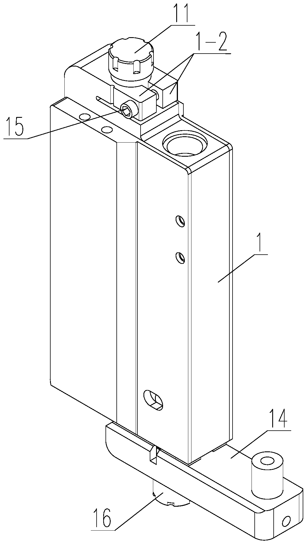
[0028] Such as Figure 1-2 As shown, a device for correcting the pre-tightening force between the striker and the nozzle, the device for correcting the pre-tightening force between the striker and the nozzle, is used for a piezoelectric injection valve, and the piezoelectric injection valve includes a valve body 1, The piezoelectric actuator 2 is arranged in the valve body 1, the striker 4 is slidably mounted on the valve body 1, and the nozzle 5 is located below the valve body 1. The piezoelectric actuator 2 drives the striker 4 through the lever 3 to amplify the driving force Feed to the nozzle 5. The device includes:
[0029] The first adjusting mechanism has a pre-tensioning member 8 and an upper adjusting block 9 and a lower adjusting block 10 that cooperate with each other. The pre-tensioning member 8 is limited to the side of the upper adjusting block 9 and can push the upper adjusting block from the side 9. The lower adjusting block 10 drives the piezoelectric actuator 2 to move down;
[0030] And the second adjustment mechanism has an adjustment rod 11 which is threadedly connected with the valve body 1, the bottom end of the adjustment rod 11 abuts on the upper surface of the upper adjustment block 9, and the adjustment rod 11 pushes the upper adjustment When the block 9 moves down, the lower adjusting block 10 drives the piezoelectric actuator 2 to move down.
[0031] The side of the valve body 1 is provided with a sliding hole 1-1, the upper adjusting block 9 and the lower adjusting block 10 are both arranged in the sliding hole 1-1, the lower surface of the upper adjusting block 9 and the lower adjusting block 10 is in contact with the upper surface, the lower surface of the upper adjustment block 9 and the upper surface of the lower adjustment block 10 are both inclined surfaces, the pretensioning member 8 abuts on the left side of the upper adjustment block 9, and the lower adjustment block The right side surface of 10 abuts against the bottom of the sliding hole 1-1, and the lower surface of the lower adjusting block 10 is opposite to the head end of the piezoelectric actuator 2.
[0032] The inclined surface is inclined upward from left to right.
[0033] The upper inner wall of the sliding hole 1-1 is a limit surface 1-11 for realizing the upper adjustment block 9 to the upper limit, and the lower surface of the lower adjustment block 10 is between the lower inner wall of the sliding hole 1-1 Leave a gap; so that when the upper adjustment block 9 is in contact with the limit surface 1-11 above the sliding hole 1-1, the upper adjustment block 9 can be restricted by the limit surface 1-11 and will not move upwards, thereby ensuring The second adjustment mechanism will not cause the piezoelectric actuator 2 to be too loose during adjustment.
[0034] The pretensioner 8 and the valve body 1 are threadedly connected.
[0035] The adjusting rod 11 has a step surface 11-1 for realizing a downward limit; thus, when the adjusting rod 11 is moved downward until its step surface 11-1 contacts the valve body 1, the step surface 11-1 can be The adjustment rod 11 is prevented from continuing to move downward, so as to ensure that the piezoelectric actuator 2 is not overtightened when the second adjustment mechanism is adjusted.
[0036] The valve body 1 has two clamping arms 1-2, the adjusting rod 11 is located between the two clamping arms 1-2, a locking screw 15 is provided on the side of the adjusting rod 11, and the locking The screw 15 is connected between the two clamping arms 1-2; the locking screw 15 is used to clamp the two clamping arms 1-2 to clamp the adjusting rod 11, thereby avoiding the loosening of the adjusting rod 11; specifically, in this embodiment , The threaded end of the locking screw 15 can pass through one clamp arm 1-2 and be screwed to the other clamp arm 1-2; or the threaded end of the locking screw 15 can pass through two clamp arms 1-2 at the same time , And screw a nut on the locking screw 15, and clamp the two clamping arms 1-2 with the nut and the nut of the locking screw 15.
[0037] Among them, the piezoelectric actuator 2 may be a piezoelectric ceramic component.
[0038] In order to explain the working principle of the present implementation more clearly, a detailed structure of a piezoelectric injection valve is provided, which can be specifically as follows: the striker 4 of the piezoelectric injection valve abuts against the lever 3 through the return spring 6, and the lever 3 is preloaded. The spring 7 abuts against the piezoelectric actuator 2, the lever 3 is installed in the valve body 1 through the fulcrum 12, the head end of the piezoelectric actuator 2 abuts against the lower adjustment block 10, the piezoelectric actuator 2 The tail end of the abutting on the lever 3, the distance between the contact point between the striker 4 and the lever 3 to the fulcrum 12>the distance between the contact point between the piezoelectric actuator 2 and the lever 3 and the fulcrum 12, the striker 4 is located on the lever Below 3, the piezoelectric actuator 2 is located above the lever 3, and the striker 4 and the piezoelectric actuator 2 are both located on the same side of the fulcrum 12;
[0039] A guide sleeve 13 is fixed at the bottom end of the valve body 1, the striker 4 is slidably arranged in the guide sleeve 13, the upper end of the return spring 6 abuts on the striker 4, and the lower end of the return spring 6 abuts in the valve body 1;
[0040] The pretension spring 7 is sleeved on the outside of the return spring 6, the upper end of the pretension spring 7 abuts against the lower surface of the lever 3, and the lower end of the pretension spring 7 abuts inside the valve body 1.
[0041] A runner body 14 is fixed below the valve body 1. The nozzle 5 is arranged at the bottom end of the runner body 14. The bottom end of the runner body 14 is screwed with a lock for pressing and fixing the nozzle 5 on the runner body 14. The cap 16 and the nozzle 5 are located in the locking cap 16, and the striker 4 passes through the runner body 14 and is opposite to the nozzle 5.
[0042] The working principle of this embodiment is as follows:
[0043] When assembling, the piezoelectric actuator 2 can be installed into the valve body 1 from the position of the adjusting rod 11 to provide a long enough installation space for the piezoelectric actuator 2; then the first adjusting structure is roughly adjusted and rotated The pre-tensioning member 8 makes the upper adjusting block 9 drive the lower adjusting block 10 to move down, and coarsely adjust the initial horizontal position of the lever 3 so that the striker 4 and the nozzle 5 are in just contact state, and there is no pre-tightening force between the striker 4 and the nozzle 5 ; Then the pre-tensioning part 8 is bonded to the valve body 1 with thread glue, so that the adjustment cannot be continued, and the pre-tensioning part 8 will not be loosened;
[0044] Among them, the end surface of the pre-tensioning member 8 and the end surface of the upper adjustment block 9 are relatively smooth, and the friction between the two is relatively small. Therefore, the pre-tensioning member 8 can completely restrict the left and right movement of the upper adjustment block 9, but cannot completely restrict the upper adjustment. Up and down movement of block 9;
[0045] The pretension spring 7 transmits the force to the upper adjustment block 9 through the lever 3, the piezoelectric actuator 2 and the lower adjustment block 10 in turn, that is, a transmission chain is formed between the pretension spring 7 and the upper adjustment block 9; That is to say, when the adjusting rod 11 is loosened, the lever 3, the piezoelectric actuator 2, the lower adjusting block 10 and the upper adjusting block 9 will be under the action of the pre-tensioning spring 7, so that the upper adjusting block 9 overcomes its and the pre-tensioning part. When the friction force between 8 moves upwards, the firing pin 4 also loosens accordingly, so as to reduce the pre-tightening force between the firing pin 4 and the nozzle 5; on the contrary, when the adjusting rod 11 is tightened, the upper adjusting block 9 will overcome The frictional force between it and the pre-tensioning member 8 moves downwards, and in turn drives the striker 4 to move down through the lower adjusting block 10, the piezoelectric actuator 2 and the lever 3, and the striker 4 is accordingly tightened accordingly. The pre-tightening force between the striker 4 and the nozzle 5 is increased.
[0046] When replacing the nozzle 5, after the nozzle 5 is reinstalled on the valve body 1, the pre-tightening force between the striker 4 and the nozzle 5 can be adjusted by rotating the adjustment lever 11; on this basis, the pre-tightening force between the striker 4 and the nozzle 5 The precise adjustment process of the pre-tightening force can be specifically as follows: the loosening or tightening of the adjusting rod 11 will affect the tightening force of the striker 4 and the nozzle 5, thereby affecting the tightness of the piezoelectric actuator 2, and the piezoelectric actuator Actuator 2 is connected to an external circuit. The current value of one path in the external circuit will also change accordingly. The change in current value is converted into a change in displacement, which can realize the pre-setting between the striker 4 and the nozzle 5. Precise adjustment of tightness.

Example Embodiment

[0047] Example 2
[0048] A piezoelectric injection valve includes the device for correcting the pre-tightening force between the striker and the nozzle in Embodiment 1.

PUM

no PUM

Description & Claims & Application Information

We can also present the details of the Description, Claims and Application information to help users get a comprehensive understanding of the technical details of the patent, such as background art, summary of invention, brief description of drawings, description of embodiments, and other original content. On the other hand, users can also determine the specific scope of protection of the technology through the list of claims; as well as understand the changes in the life cycle of the technology with the presentation of the patent timeline. Login to view more.

Similar technology patents

Fabricated wall body

Owner:BEIJING NEW BUILDING MATERIAL

Connecting structure for motorcycle plastic covering parts

InactiveCN105216916Aeven seamReduce the difficulty of assembly
Owner:力帆科技(集团)股份有限公司

Magnetic suspension bearing stator, magnetic suspension bearing, motor, compressor and air conditioner

PendingCN110056575AAvoid multiple disassemblyReduce the difficulty of assembly
Owner:GREE ELECTRIC APPLIANCES INC OF ZHUHAI +1

Air conditioner and fan thereof

PendingCN109268940AReduce the number of settingsReduce the difficulty of assembly
Owner:GREE ELECTRIC APPLIANCES INC OF ZHUHAI

Electric instructional car transmission system

PendingCN111959266AEnsure coaxial assembly accuracyReduce the difficulty of assembly
Owner:DONGFENG AUTOMOBILE COMPANY

Classification and recommendation of technical efficacy words

  • Reduce the difficulty of assembly
  • Improve maintenance efficiency

Mobile terminal

InactiveCN106887695AImprove contact reliabilityReduce the difficulty of assembly
Owner:JRD COMM

Method for preparing lens module

InactiveCN102109650AReduce the use of moldsReduce the difficulty of assembly
Owner:HONG FU JIN PRECISION IND (SHENZHEN) CO LTD +1

Cladding system of fusion-fission reactor

Owner:INST OF NUCLEAR PHYSICS & CHEM CHINA ACADEMY OF

Gas release device and unmanned aerial vehicle

PendingCN109436342AAvoid Spring AgingReduce the difficulty of assembly
Owner:北京科新信息技术有限公司

Radio-frequency coaxial connector with connector assembly

PendingCN109742615AGood RF electrical performanceReduce the difficulty of assembly
Owner:广东国昌科技有限公司
Why Eureka
Try Eureka