Machine tool scrap iron collecting device

A technology for collecting device and iron filings, which is applied in the direction of metal processing machinery parts, maintenance and safety accessories, metal processing equipment, etc. It can solve the problems of collecting iron filings that cannot be directly solved in one step, so as to reduce costs and reduce mechanical equipment glitch effect

Inactive Publication Date: 2019-12-10
徐州米特机械制造有限公司
View PDF8 Cites 1 Cited by
  • Summary
  • Abstract
  • Description
  • Claims
  • Application Information

AI Technical Summary

Problems solved by technology

[0003] The existing patent document CN204603941U discloses a machine tool chip collection device. This device provides a machine tool chip collection device that uses a chip collection hopper to collect chips and a screw mechanism to transport the chips. However, this collection device still requires personnel to move the machine tool After the iron filings generated on the machine are collected and put into the scrap collecting hopper, the scrap can be collected and sorted. It cannot solve the problem of scrap collection on machine tools directly in one step.

Method used


Image

  • Machine tool scrap iron collecting device
  • Machine tool scrap iron collecting device
  • Machine tool scrap iron collecting device

Examples


Embodiment Construction

[0021] The following will clearly and completely describe the technical solutions in the embodiments of the present invention with reference to the accompanying drawings in the embodiments of the present invention. Obviously, the described embodiments are only some, not all, embodiments of the present invention.

[0022] In describing the present invention, it should be understood that the terms "upper", "lower", "front", "rear", "left", "right", "top", "bottom", "inner", " The orientation or positional relationship indicated by "outside", etc. is based on the orientation or positional relationship shown in the drawings, and is only for the convenience of describing the present invention and simplifying the description, rather than indicating or implying that the referred device or element must have a specific orientation, so as to Specific orientation configurations and operations, therefore, are not to be construed as limitations on the invention.

[0023] refer to Figure ...


PUM


Abstract

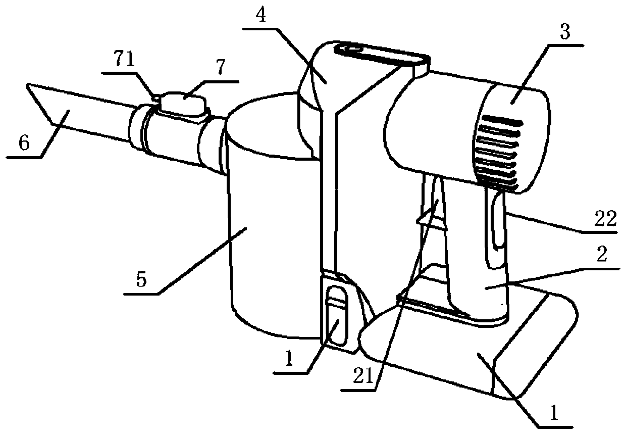
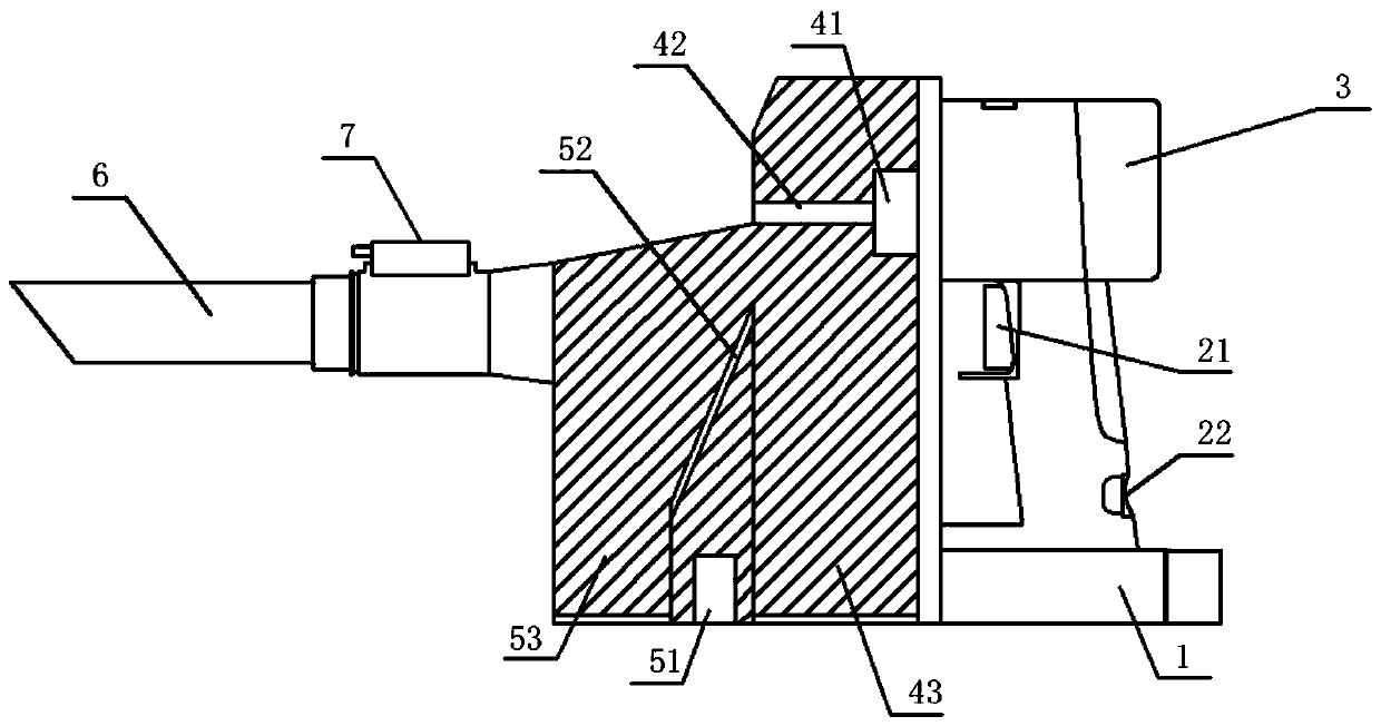
The invention discloses a machine tool scrap iron collecting device. The device is characterized by comprising a base, a handle, an air suction pump, a dust separating box, a scrap iron separating box, a suction inlet and an illumination controller, wherein the handle is arranged on the upper part of one end of the base; the air suction pump is mounted on the upper part of one end of the handle; the dust separating box is arranged on the left side of one end of the air suction pump; the scrap iron separating box is connected to the left side of one end of the dust separating box; the suction inlet is formed in the left side of one end of the scrap iron separating box; and the illumination controller is mounted on the upper part. According to the device, scrap iron is separated from dust byusing an electromagnet of a scrap iron separating box, thus achieving the effect of full absorption by separation; and meanwhile, and has strong maneuverability of a handheld device is high in maneuverability and can work at any position on a machine tool, so that the function of fully absorbing and cleaning can be achieved.

Description

technical field [0001] The invention relates to the field of machine tool mechanical equipment, in particular to a machine tool scrap collecting device. Background technique [0002] During the processing of iron parts, various machine tools used in machining workshops inevitably produce a large amount of iron filings, which are scattered everywhere, which will affect the normal operation of the equipment and production safety, and iron filings scattered on the ground are very dangerous. It is easy to injure the feet of the operator, seriously affect the life safety of the staff, and also affect the working environment. If these generated iron filings can be well collected, it can not only be recycled, reduce production costs, but also create a good environment for the production workshop. [0003] The existing patent document CN204603941U discloses a machine tool chip collection device. This device provides a machine tool chip collection device that uses a chip collection ...

Claims


Application Information

Patent Timeline
IPC IPC(8): B23Q11/00
CPCB23Q11/00B23Q11/0046B23Q11/0064
Inventor 刘建设
Owner 徐州米特机械制造有限公司
Why Eureka
Try Eureka