A grinding device for construction engineering and its working method

A construction engineering and roller technology, applied in grinding drive devices, grinding/polishing safety devices, grinding machines, etc., can solve the problems of polluting the environment, inconvenience, damage to the health of workers, etc., to protect the air, reduce the handling height, reduce the effect of noise

Active Publication Date: 2021-01-22
江西志帮实业有限公司
View PDF9 Cites 0 Cited by
  • Summary
  • Abstract
  • Description
  • Claims
  • Application Information

AI Technical Summary

Problems solved by technology

[0003] However, when grinding the surface of the slate, a large amount of dust will be generated. Most of the existing grinding equipment has no dust removal effect. The grinding dust not only floats in the air, but also falls on the surface of the equipment and the ground, which not only pollutes the environment, but also damages the work. Personnel health
At the same time, during the grinding process, it is very inconvenient to adjust the position of the slate. The existing grinding device requires a lot of manual labor to operate, which makes the labor intensity of the workers very high, which is not conducive to the efficiency of grinding.

Method used


Image

  • A grinding device for construction engineering and its working method
  • A grinding device for construction engineering and its working method
  • A grinding device for construction engineering and its working method

Examples


Embodiment Construction

[0021] The following will clearly and completely describe the technical solutions in the embodiments of the present invention with reference to the accompanying drawings in the embodiments of the present invention. Obviously, the described embodiments are only some, not all, embodiments of the present invention. Based on the embodiments of the present invention, all other embodiments obtained by persons of ordinary skill in the art without making creative efforts belong to the protection scope of the present invention.

[0022] In the description of the present invention, it should be noted that the terms "center", "upper", "lower", "left", "right", "vertical", "horizontal", "inner", "outer" etc. The indicated orientation or positional relationship is based on the orientation or positional relationship shown in the drawings, and is only for the convenience of describing the present invention and simplifying the description, rather than indicating or implying that the referred d...


PUM


Abstract

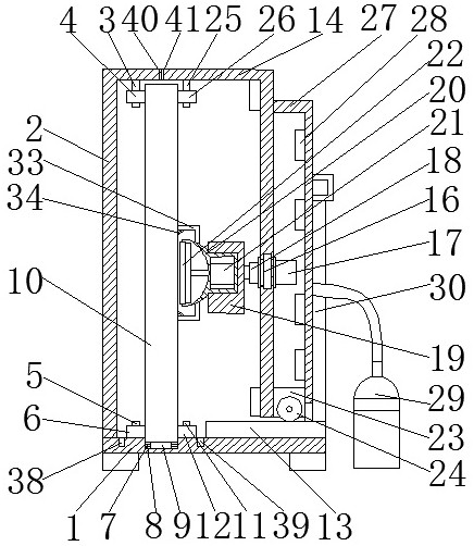
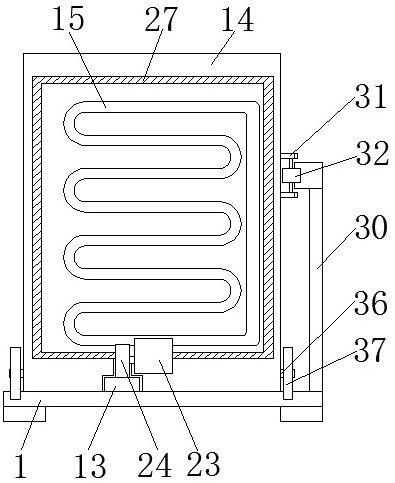
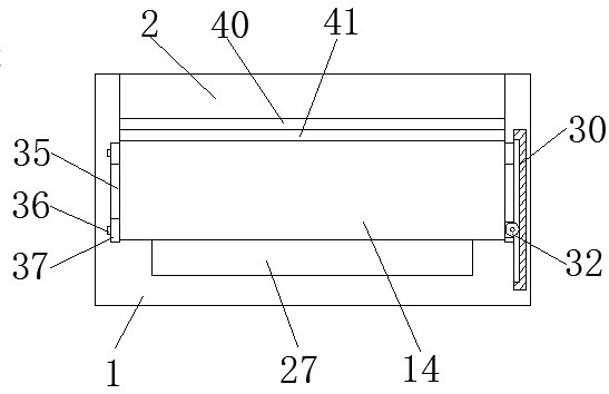
The invention discloses a polishing device for construction engineering and a working method thereof. The polishing device comprises a base, the upper surface of the base is fixedly connected with a left box body, the position, in the upper portion, of the inner surface of the left box body is fixedly connected with a first rotating shaft, a first rolling wheel is rotationally connected with the outer surface of the first rotating shaft, a second rotating shaft is fixedly connected to the upper surface of the base, a second rolling wheel is rotationally connected to the outer surface of the second rotating shaft, a movable groove is formed in the upper surface of the base, a movable shaft is fixedly connected to the inner surface of the movable groove, a roller is rotationally connected tothe outer surface of the movable shaft, and a stone plate is arranged at the position, on the left side of the second rolling wheel, of the upper portion of the roller. According to the polishing device for construction engineering and the working method thereof, the closed structure is adopted, so that the dust escape is greatly reduced, the influence of noise during grinding on a worker is alsoreduced, the stone plate is polished in a vertical mode, so that the working mode by which a stone plate is lifted to a working table at a higher position is replaced, and the fatigue degree of the worker is reduced.

Description

technical field [0001] The invention relates to the technical field of stone slab processing, in particular to a grinding device for construction engineering and a working method thereof. Background technique [0002] In building decoration materials, slate can be seen everywhere and is widely used. Whether it is natural slate or synthetic slate, the surface is generally rough and needs to be polished to obtain a radiant effect. [0003] However, when grinding the surface of the slate, a large amount of dust will be generated. Most of the existing grinding equipment has no dust removal effect. The grinding dust not only floats in the air, but also falls on the surface of the equipment and the ground, which not only pollutes the environment, but also damages the work. Personnel health. At the same time, during the grinding process, it is very inconvenient to adjust the position of the slate. The existing grinding device requires a lot of manual effort to operate, which makes...

Claims


Application Information

Patent Timeline
Patent Type & Authority Patents(China)
IPC IPC(8): B24B7/22B24B55/00B24B41/02B24B55/06B24B41/00B24B41/06B24B47/12
CPCB24B7/222B24B41/005B24B41/02B24B41/06B24B47/12B24B55/00B24B55/06
Inventor 陈好学
Owner 江西志帮实业有限公司
Why Eureka
Try Eureka