Yarn connection device

A technology of negative pressure device and yarn bobbin, which is applied in the field of yarn splicing device and automatic yarn splicing device

Active Publication Date: 2019-12-10
DONGHUA UNIV +1
View PDF10 Cites 12 Cited by
  • Summary
  • Abstract
  • Description
  • Claims
  • Application Information

AI Technical Summary

Problems solved by technology

[0006] The purpose of the present invention is to solve the problem that the yarn joining device in the prior art is not suitable for textile machines whose yarn joining path is a complex three-dimensional route, and to provide a yarn jointing device with high efficiency, which can automatically find broken ends of yarns, and is suitable for use in three-dimensional space. An automatic yarn splicing device that has complex wiring routes and realizes that one device can provide services for multiple yarns

Method used


Image

  • Yarn connection device
  • Yarn connection device
  • Yarn connection device

Examples


Embodiment Construction

[0069] The present invention will be further described below in combination with specific embodiments. It should be understood that these examples are only used to illustrate the present invention and are not intended to limit the scope of the present invention. In addition, it should be understood that after reading the teachings of the present invention, those skilled in the art can make various changes or modifications to the present invention, and these equivalent forms also fall within the scope defined by the appended claims of the present application.

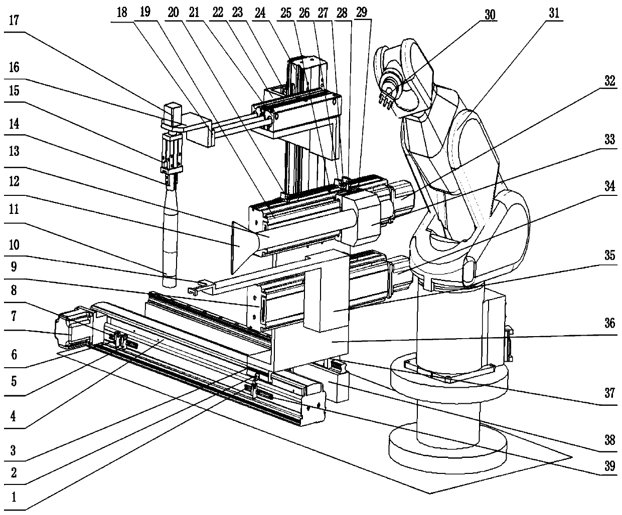
[0070] In all descriptions of the present invention, it should be noted that the determination of the direction of motion is based on the attached figure 1 The directions of the X, Y, and Z axes respectively represented by the middle main guide rail slide frame 4, the upper linear guide rail slide frame 19, and the linear guide rail slide frame γ24 are standard, and the terms "front", "top view", "left view" and "right ...


PUM


Abstract

The invention relates to a yarn connection device. The device comprises a spool clamping hand part, a driving system I, a suction nozzle assembly, a negative pressure device, a driving system II, a magnetic fixing body, a driving system III, a yarn clamping hand part and an industrial robot; the driving system I is used for driving the spool clamping hand part to move along the X axis, Y axis andZ axis of the space rectangular coordinate system, clamp a spool, release the spool and rotate around the axis of the spool clamping hand part; the driving system II is used for driving the suction nozzle assembly to move along the X axis and the Y axis and driving the negative pressure device to generate negative pressure so as to suck a broken yarn end on the spool to a to-be clamped position; the driving system III is used for driving the magnetic fixing body to move along the X axis and Y axis so as to stir a steel wire ring to the designated position; the industrial robot is used for driving the yarn clamping hand part to clamp the broken yarn end, hang the broken yarn end at the steel wire ring, an air loop ring and a guide wire in sequence, put the broken yarn end into a front roller jaw of a spinning frame and loosen the broken yarn end. The yarn connection device can conduct yarn connection work of complex three-dimensional routes.

Description

technical field [0001] The invention belongs to the technical field of textile machinery and relates to a yarn joining device, in particular to a device for automatically joining yarns after a spinning frame breaks. Background technique [0002] After the existing spinning frame breaks, the mainstream of the yarn splicing technology is to manually resplice the yarn, that is, the worker takes out the broken spindle, manually finds the broken end of the yarn, and then uses the traditional pinching method. , reconnect the broken thread and continue spinning. This technology requires high proficiency of workers, cumbersome operation, easy to pollute the yarn, and low automation level. Manually find the broken end of the yarn, and then connect it, and the error rate is high. , The quality of the wiring is poor, the efficiency is low, and time is wasted. [0003] Patent CN105568455A discloses a broken wire automatic splicer, which pulls the front end of the broken wire back into ...

Claims


Application Information

Patent Timeline
Patent Type & Authority Applications(China)
IPC IPC(8): D01H15/013
CPCD01H15/013
Inventor 周其洪孙宝通岑均豪陈革孙志宏占齐宸
Owner DONGHUA UNIV
Why Eureka
Try Eureka