Yarn guide device of seamless underwear knitting machine

A technology of seamless knitted underwear and yarn guide device, which is applied in knitting, weft knitting, textiles and papermaking, etc. It can solve the problems of affecting product quality and poor dust removal effect at dust outlet points, and achieve the effect of avoiding yarn entanglement

Inactive Publication Date: 2019-12-10
义乌市欧秀服饰有限公司
View PDF0 Cites 4 Cited by
  • Summary
  • Abstract
  • Description
  • Claims
  • Application Information

AI Technical Summary

Problems solved by technology

[0003] During the production and processing of most knitted underwear machines, the yarn will generate a certain amount of floating dust. In the prior art, only a large area of ​​dust is removed for the equipment, and the effect of dust removal on local dust outlet points is not good, and manual cleaning is required. The operator brings certain inconvenience. At the same time, the yarn guiding and feeding mechanism in the knitting underwear machine directly affects the quality of the product. The yarn guiding and feeding mechanism in the prior art cannot be well adapted to yarns of different sizes. Use, and dust removal and tension adjustment for it are not very easy to use

Method used


Image

  • Yarn guide device of seamless underwear knitting machine
  • Yarn guide device of seamless underwear knitting machine
  • Yarn guide device of seamless underwear knitting machine

Examples


Embodiment 1

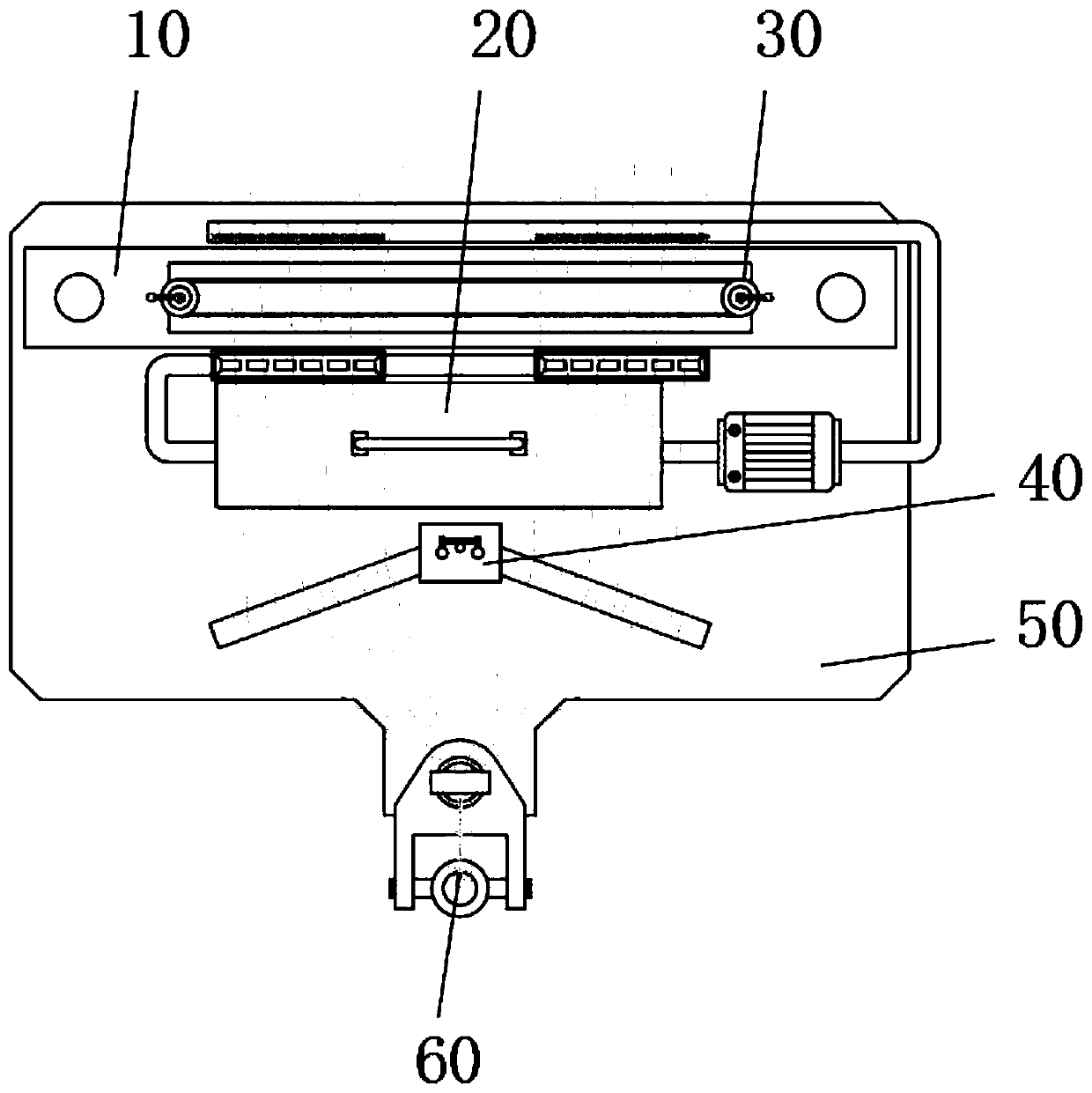
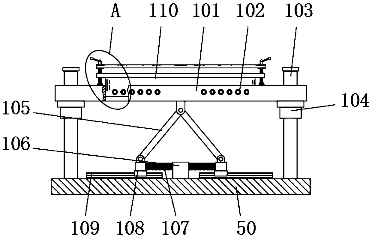
[0036] Embodiment one, with reference to Figure 1-4, a yarn guide device for a seamless knitted underwear machine, comprising an adjustment mechanism 10, a dust removal mechanism 20, a synchronization mechanism 30, a yarn feeding mechanism 40, a bottom plate 50 and a thread winding mechanism 60, the top surface of the adjustment mechanism 10 is provided with a synchronization mechanism 30, and The bottom of the adjustment mechanism 10 is fixed on the base plate 50, and one side of the adjustment mechanism 10 is provided with a yarn feeding mechanism 40 and a thread gathering mechanism 60 in sequence, and the bottoms of the yarn feeding mechanism 40 and the thread gathering mechanism 60 are all fixed on the bottom plate 50, and the adjustment mechanism 10 includes The first yarn guide plate 101, optical axis 103, guide sleeve 104, connecting rod 105, fixed block 106, adjustment spring 107, slide block 108, guide rail 109 and the second yarn guide plate 110, the first yarn guide...

Embodiment 2

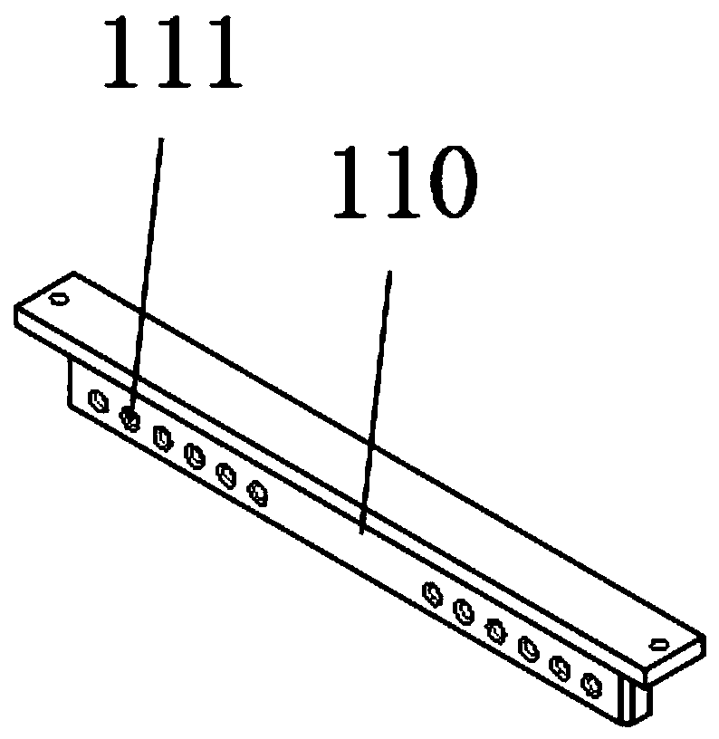
[0037] Embodiment two, refer to figure 2 and Figure 7 , both ends of the second yarn guide plate 110 are threadedly connected with the adjustment screw rod 301, and the bottom of the adjustment screw rod 301 is fixed on the first yarn guide plate 101 through the bearing seat 305, and the upper ends of the adjustment screw rod 301 are respectively equipped with pulleys 302 There are two adjustment handles 303 and pulleys 302, and the two pulleys 302 are connected through a timing belt 304 transmission. When adjusting, turn any adjustment handle 303, and under the action of the pulley 302 and the timing belt 304 , so that the adjusting screw 301 fixed at both ends of the first yarn guide plate 101 through the bearing housing 305 rotates at the same time, so that the moving second yarn guide plate 101 is always kept parallel to the first yarn guide plate 110 when it is adjusted up and down, ensuring that the guide normal operation of yarn.

Embodiment 3

[0038] Embodiment three, refer to Figure 5 and Figure 6 , the dust removal mechanism 20 comprises a dust collecting box 201, an air exhaust pipe 202, a blower fan 204, and an air outlet pipe 205. The air outlets 206 are all corresponding to the positions of the outer guide holes 102. The inside of the dust collection box 201 is provided with a sliding drawer box 207, and the inside of the drawer box 207 is provided with a cloth bag 208 and a filter screen 209. When removing dust, start the blower fan 204, Blow air through the blower fan 204 into the air outlet pipe 205, and blow it into the outer yarn guide hole 102 and the inner yarn guide hole 111 from the blower port 206, and blow the yarn hoard, sand grains and other sundries scraped off from the yarn inside it. To the air outlet 203 at the other end, by the air outlet 203, debris such as yarn storage and sand grains are collected, and transported to the inside of the dust box 201 along the air exhaust pipe 202, through...


PUM


Abstract

The invention discloses a yarn guide device of a seamless underwear knitting machine. The yarn guide device comprises an adjusting mechanism, a dust removal mechanism, a synchronous mechanism, a yarnfeeding mechanism, a bottom plate and a thread gathering mechanism. The synchronous mechanism is arranged on the top face of the adjusting mechanism. The bottom of the adjusting mechanism is fixed tothe bottom plate. The yarn feeding mechanism and the thread gathering mechanism are sequentially arranged on one side of the adjusting mechanism. In the yarn guide device, by means of the adjusting mechanism, yarn can be kept in a straightened state all the time, and the surface of the yarn of different specifications can be cleaned. When the yarn penetrating through an outer yarn guide hole bearslarge tensile force, a first yarn guide plate can be automatically moved and adjusted downwards along the optical axis under the effect of the yarn. One end of a connecting rod is connected with thefirst yarn guide plate through a hinge base, the other end of the connecting rod is hinged to the top face of a slider, and therefore an adjusting spring connected with the side face of the slider hasa buffering and adjusting effect, it is ensured that the yarn penetrating through the first yarn guide plate is kept in a straightened state all the time, and the yarn winding phenomenon during the work of a yarn guide hook is avoided.

Description

technical field [0001] The invention relates to the technical field of knitting, in particular to a yarn guide device for a seamless knitted underwear machine. Background technique [0002] The process of using knitting needles to form coils of various raw materials and varieties of yarns, and then connecting them into knitted fabrics through string sleeves. The knitted fabric is soft in texture, has good wrinkle resistance and air permeability, and has greater extensibility and elasticity, making it comfortable to wear. Seamless weaving is synonymous with comfort. It can realize the best combined application of various natural fibers, man-made fibers and synthetic fibers. The seamless products fit the skin and the neck, waist and hips are seamlessly connected, making the wearing more comfortable and natural. [0003] During the production and processing of most knitted underwear machines, the yarn will generate a certain amount of floating dust. In the prior art, only a la...

Claims


Application Information

Patent Timeline
Patent Type & Authority Applications(China)
IPC IPC(8): D04B15/48D04B15/58D04B35/32D04B35/22
CPCD04B15/48D04B15/58D04B35/22D04B35/32
Inventor 陈海雄任大龙王起
Owner 义乌市欧秀服饰有限公司
Why Eureka
Try Eureka