Plant chlorophyll fluorescence parameter correction method and device

A technology of chlorophyll fluorescence and correction device, which is applied in the field of plant phenotype analysis, and can solve the problems of reduced accuracy, deviation of fluorescence yield, disadvantages, etc.

Pending Publication Date: 2019-12-10
FUJIAN AGRI & FORESTRY UNIV
View PDF0 Cites 3 Cited by
  • Summary
  • Abstract
  • Description
  • Claims
  • Application Information

AI Technical Summary

Benefits of technology

This technology solves problems that occur when measuring greenhouse gas levels due to fluctuations or shifts between weather cycles during growth time periods for crops like rice. It also helps predict how well certain types of crop will be able produce high amounts of nitrogen fertilizers without losing their ability to absorb sunlight needed for photosynthetic activity. Overall, this new technology improves understanding on vegetation's biological processes while reducing environmental impact associated therewith.

Problems solved by technology

The technical problem addressed by this patented technology relates to accurately detecting changes made during photosyntactic process caused by movements or aggregating substances that affect how well certain parts of plants absorb sunlight for photosynthate production. This helps identify those having better performance than others from other crops being grown on top.

Method used


Image

  • Plant chlorophyll fluorescence parameter correction method and device
  • Plant chlorophyll fluorescence parameter correction method and device
  • Plant chlorophyll fluorescence parameter correction method and device

Examples


Embodiment

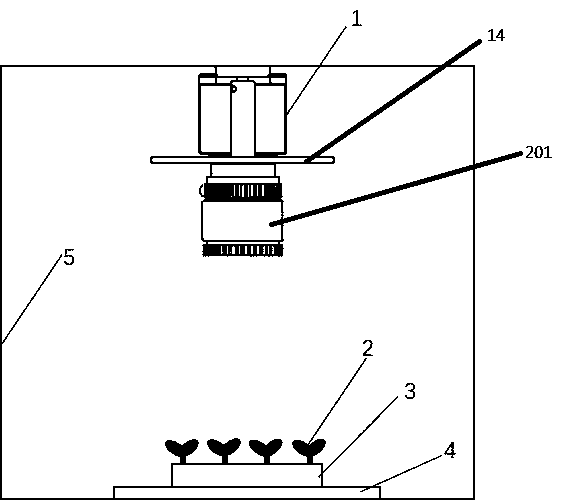
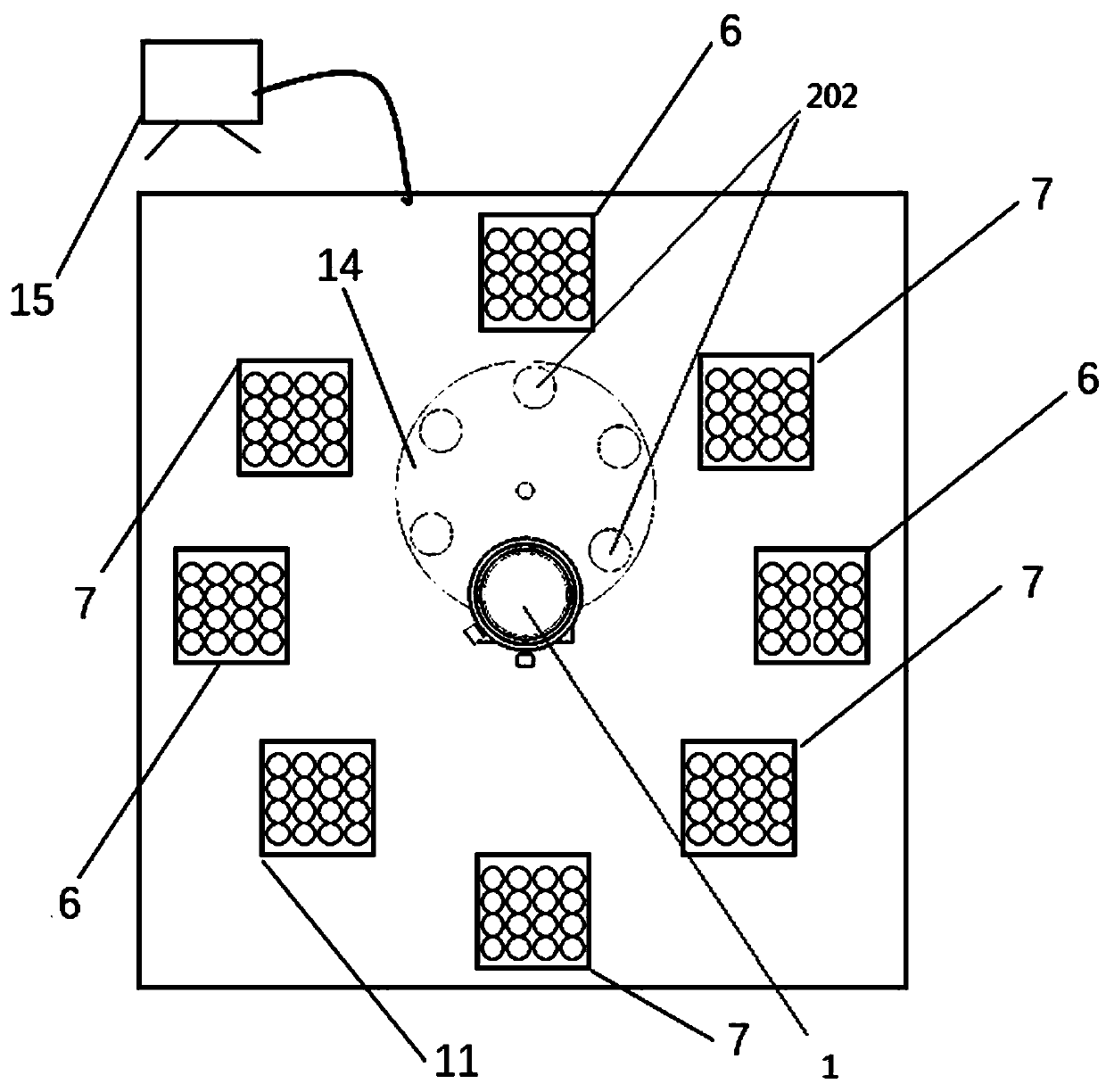
[0054] like figure 1 As shown, the device of the method for correcting chlorophyll fluorescence parameters includes an imaging system consisting of a CCD monochrome camera 1 , a 10 mm lens, and a filter wheel 14 . Six working positions on the filter wheel, including 680 nm bandpass filter, narrow band 440nm, 520 nm, 690 nm and 740 nm filters, and zero position (no filter). 680nm bandpass filter, filter for dynamic fluorescence measurement, narrowband 440 nm, 520 nm, 690 nm and 740 nm filter for multispectral fluorescence measurement, zero (no filter installed) for red Light reflectance image acquisition. Plants 2 of different genotypes are planted in the tray 3 in the same manner, and the tray is placed on the conveyor belt 4, so that plants in different trays can all enter the field of view of the camera. In order to obtain dynamic fluorescence, steady-state fluorescence and red light reflectance images, the system provides 4 actinic light sources (620 nm) and 4 ultraviolet...


PUM

PropertyMeasurementUnit
Center wavelengthaaaaaaaaaa

Abstract

The invention provides a plant chlorophyll fluorescence parameter correction method and device. The method comprises A1, carrying out dark adaptation treatment on a plant; A2, acquiring a minimum chlorophyll fluorescence image of the plant, and then acquiring a maximum chlorophyll fluorescence image of the plant; A3, enabling the plant to be in an actinic light irradiation environment, and obtaining an initial reflection image of the plant at the moment; A4, irradiating the plant with actinic light for t hours, and obtaining a plant reflection image and a dynamic instantaneous fluorescence image after the plant reaches a light adaptation state; A5, after the plants are illuminated by ultraviolet light for t hours, obtaining a steady-state blue spectral fluorescence image, a green spectralfluorescence image, a red spectral fluorescence image and a far infrared spectral fluorescence image of the plant; A6, calculating a chlorophyll fluorescence yield deviation coefficient; A7, carryingout correction calculation to obtain an actual chlorophyll fluorescence yield parameter under an illumination condition; A8, calculating to obtain an actual chlorophyll fluorescence parameter image for analysis. The photosynthesis efficiency can be detected more accurately by the method and the device.

Description


Claims


Application Information

Patent Timeline
Owner FUJIAN AGRI & FORESTRY UNIV
Why Eureka
Try Eureka