Microwave anechoic chamber far-field test system

A microwave anechoic chamber and far-field testing technology, which is applied in the testing field to achieve the effect of quick deployment and convenient later upgrade and transformation

Pending Publication Date: 2019-12-10
FRAGRANT MOUNTAIN MICROWAVE CO LTD
View PDF0 Cites 8 Cited by
  • Summary
  • Abstract
  • Description
  • Claims
  • Application Information

AI Technical Summary

Problems solved by technology

This structure is powerless for the test of large antennas

Method used


Image

  • Microwave anechoic chamber far-field test system
  • Microwave anechoic chamber far-field test system
  • Microwave anechoic chamber far-field test system

Examples


Embodiment Construction

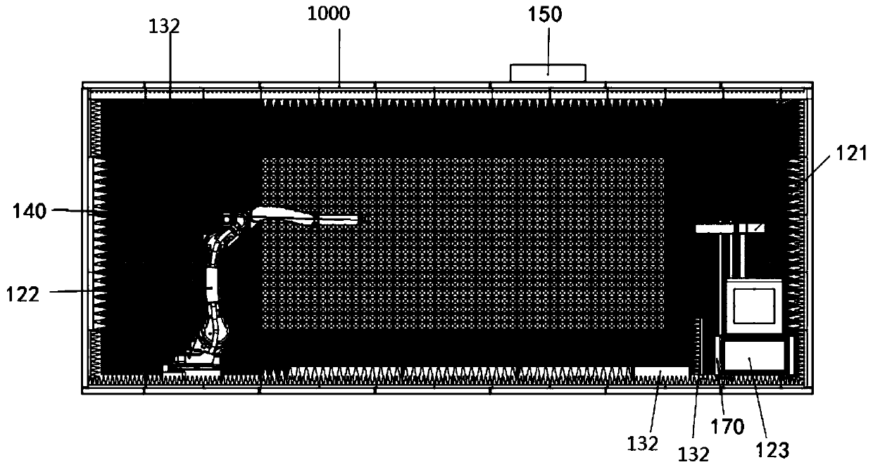
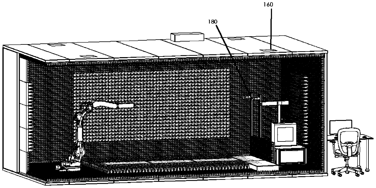
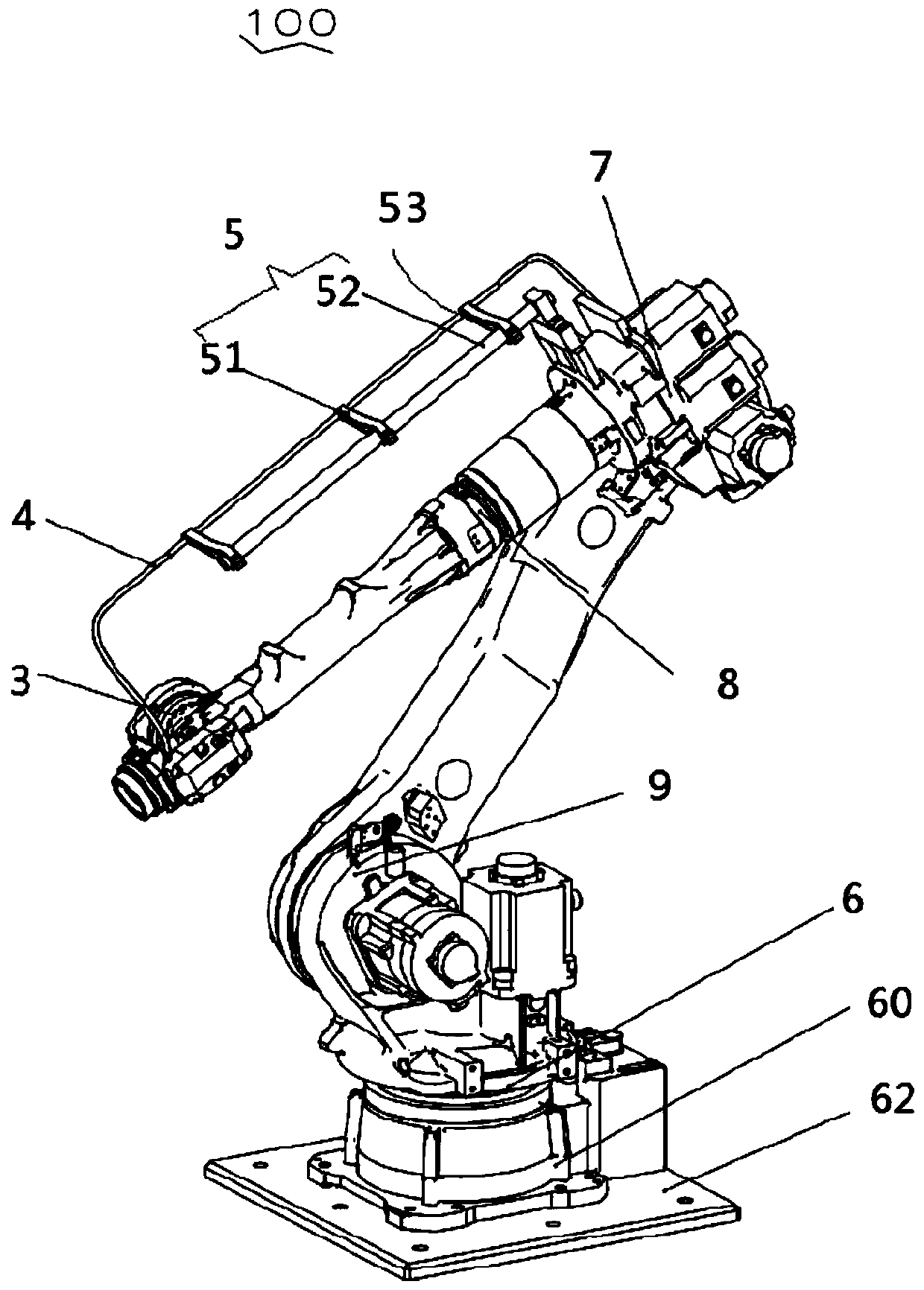
[0029] see figure 1 and figure 2 , the microwave anechoicroom far-field testing system of the present application includes a microwave anechoicroom 1000, antenna test turntables 121 and 122, a radio frequency signal link (not marked), and a control center (not shown in the figure), and the control center may be a computer. The antenna test turntables 121 and 122 are set in the microwave anechoic room 1000, and the microwave anechoic room is set in a shielding room, generally an aluminum-plastic shielding room. The radio frequency signal link connects the antenna test turntable and the control center, and the antenna test turntable includes a transmitting antenna turntable 121 and a receiving antenna turntable 122, and the receiving antenna turntable 122 is a robot turntable. In a specific embodiment, the receiving antenna turntable 122 is a six-axis robot turntable, and the transmitting antenna turntable 121 is arranged on a turntable base 123 . The test product 140 is plac...


PUM


Abstract

The invention provides a microwave anechoic chamber far-field test system. The system comprises a microwave anechoic chamber, an antenna test rotary table, a radio frequency signal link and a controlcenter, the antenna test rotary table is arranged in the microwave anechoic chamber, the radio frequency signal link is connected with the antenna test rotary table and the control center, the antennatest rotary table comprises a transmitting antenna rotary table and a receiving antenna rotary table, and the receiving antenna rotary table is a robot rotary table. The six-axis industrial robot isadopted to realize large-range, high-degree-of-freedom and high-precision antenna radiation parameter measurement.

Description

【Technical field】 [0001] The present application relates to the technical field of testing, in particular to an antenna testing system. 【Background technique】 [0002] With the advancement of technology, electronic devices such as mobile phones have been widely popularized. Electronic devices often include antennas to communicate with other electronic devices. Before the electronic device leaves the factory, or when the electronic device is being repaired, the performance of the antenna in the electronic device is often tested to determine whether the antenna is qualified. In the traditional technology, more test instruments are usually used when testing the antenna in the electronic device. [0003] Antenna test system is a set of automatic test system for antenna radiation field scanning, data collection, test data processing and test result display and output under the control of central computer. The whole antenna far-field test system consists of two parts: hardware ...

Claims


Application Information

Patent Timeline
Patent Type & Authority Applications(China)
IPC IPC(8): G01R29/10
CPCG01R29/105
Inventor 东君伟冼育览毛记平黄桂华
Owner FRAGRANT MOUNTAIN MICROWAVE CO LTD
Why Eureka
Try Eureka