Continuous automatic stamping die and stamping method thereof

A stamping die, automatic technology, applied in the field of stamping die, can solve the problems of prolonged production time, inability to complete stamping, affecting production cost, etc., to achieve the effect of improving quality, improving work efficiency, and improving stamping efficiency

Active Publication Date: 2019-12-13
赵宝宏
View PDF11 Cites 11 Cited by
  • Summary
  • Abstract
  • Description
  • Claims
  • Application Information

AI Technical Summary

Problems solved by technology

And all products are produced by moulds. If you want to improve efficiency and reduce costs, you need to reduce the cost of molds first, and let the molds have the highest efficiency in production, so as to achieve the lowest cost and the highest benefit. , the traditional mold is processed one process after another, and it is impossible to complete the stamping of different processes at the same time, so that in the production process, the production time is extended, and the operator's working time and Intensity, naturally the cost to pay will increase. If mass production, then the cost will be very large, which directly affects the production cost
Moreover, this production mode not only affects the production cost, but also leads to low production efficiency and poor effect of continuous stamping
Moreover, the existing stamping dies cannot maintain the stability of the material during stamping, which affects the efficiency of stamping

Method used


Image

  • Continuous automatic stamping die and stamping method thereof
  • Continuous automatic stamping die and stamping method thereof
  • Continuous automatic stamping die and stamping method thereof

Examples


Embodiment Construction

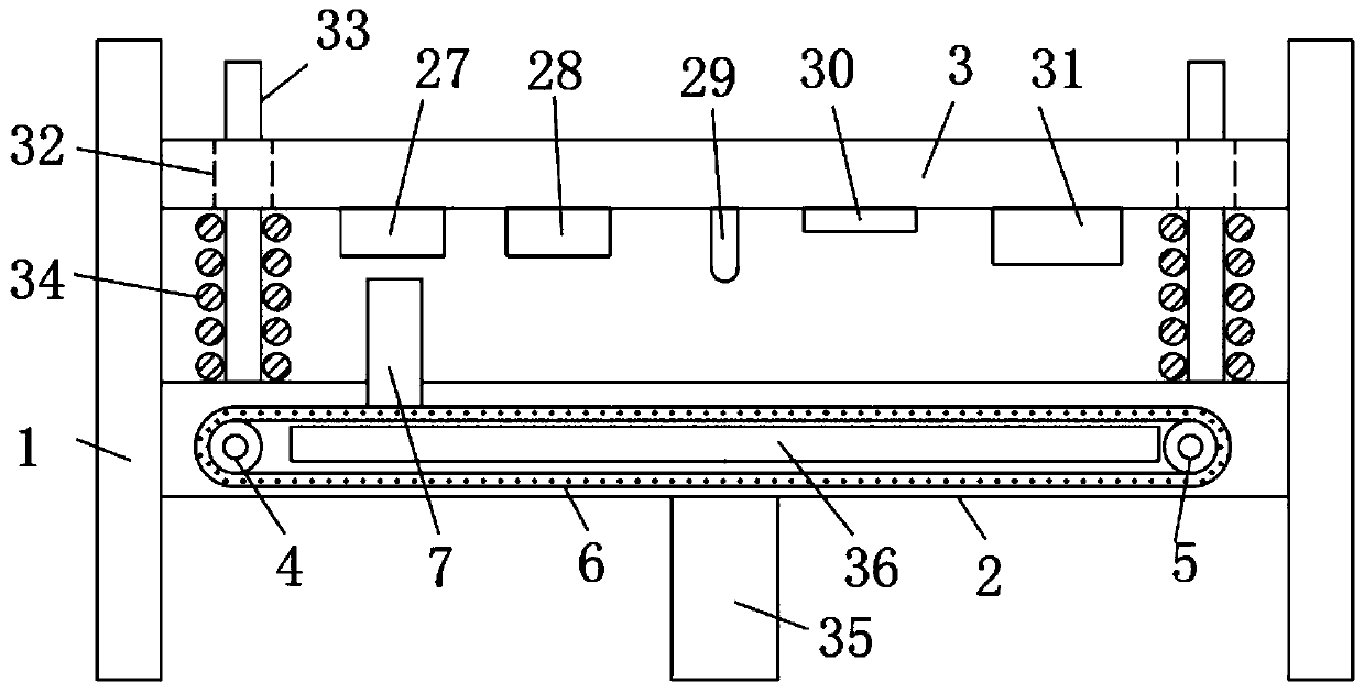
[0031] The present invention provides such Figure 1-4 A continuous automatic stamping die shown, such as figure 1As shown, it includes a support plate 1, two support plates 1 are provided, and the two support plates 1 are fixedly connected by a lower formwork 2, the lower formwork 2 is located at the lower end of the support plate 1, and an upper formwork 3 is arranged above the lower formwork 2 , one end on both sides of the lower template 2 is provided with a driving roller 4, and the driving roller 4 is connected with a driving device embedded in the lower template 2 through a transmission shaft. The driving device is a servo motor, and the other end on both sides of the lower template 2 is provided with The drive roller 5 is movably connected with the lower template 2 through the connecting shaft, and the drive roller 4 and the drive roller 5 on the same side are connected through the conveyor belt 6. The cooperation between the drive roller 4 and the drive roller 5 can d...


PUM


Abstract

The invention discloses a continuous automatic stamping die, and belongs to the technical field of stamping dies. The technical essential is as follows: the continuous automatic stamping die comprisessupport plates, wherein two support plates are arranged; the two support plates are fixedly connected through a lower die plate; an upper die plate is arranged above the lower die plate; a drive rollis arranged at one end of each of the two sides of the lower die plate; the drive rolls are connected with a drive device inlaid in the lower die plate through transmission shafts; a transmission roll is arranged at the other end of each of the two sides of the lower die plate; the transmission rolls are movably connected with the lower die plate through connection shafts; the drive roll and thetransmission roll which are located at the same side are connected through a conveying belt; and a clamping assembly is arranged at one end of the upper surface of each conveying belt. According to the continuous automatic stamping die, the drive rolls, the transmission rolls and the conveying belts are arranged at the two sides of the lower die plate, the clamping assemblies can be driven to move, a cylinder is arranged on each clamping assembly, and each clamping assembly is enabled to stably clamp a stamping material; and each cylinder is configured to be of a movable structure, so that thestamping material is capable of driving the cylinder to move during stamping working.

Description

technical field [0001] The invention relates to the field of stamping dies, more specifically, to a continuous automatic stamping die and a stamping method thereof. Background technique [0002] With the continuous innovation and development of human beings, time has become more and more precious. For current manufacturers, in addition to sales volume, cost and benefit are the most important aspects of producing a product. And all products are produced by moulds. If you want to improve efficiency and reduce costs, you need to reduce the cost of molds first, and let the molds have the highest efficiency in production, so as to achieve the lowest cost and the highest benefit. , the traditional mold is processed one process after another, and it is impossible to complete the stamping of different processes at the same time, so that in the production process, the production time is extended, and the operator's working time and Intensity, the cost to pay will naturally increase....

Claims


Application Information

Patent Timeline
Patent Type & Authority Applications(China)
IPC IPC(8): B21D37/08B21D35/00B21D43/00B21D43/12
CPCB21D35/001B21D35/002B21D37/08B21D43/003B21D43/12
Inventor 姚长春刘志宾李建明吴志强董明华
Owner 赵宝宏
Why Eureka
Try Eureka