

Automatic steel plate welding mechanical arm
An automatic welding and robotic arm technology, applied in the field of robotic arms, can solve the problems of easy displacement of steel plate and complicated operation
- Summary
- Abstract
- Description
- Claims
- Application Information
AI Technical Summary
Problems solved by technology
Method used
Image

Examples
Embodiment 1
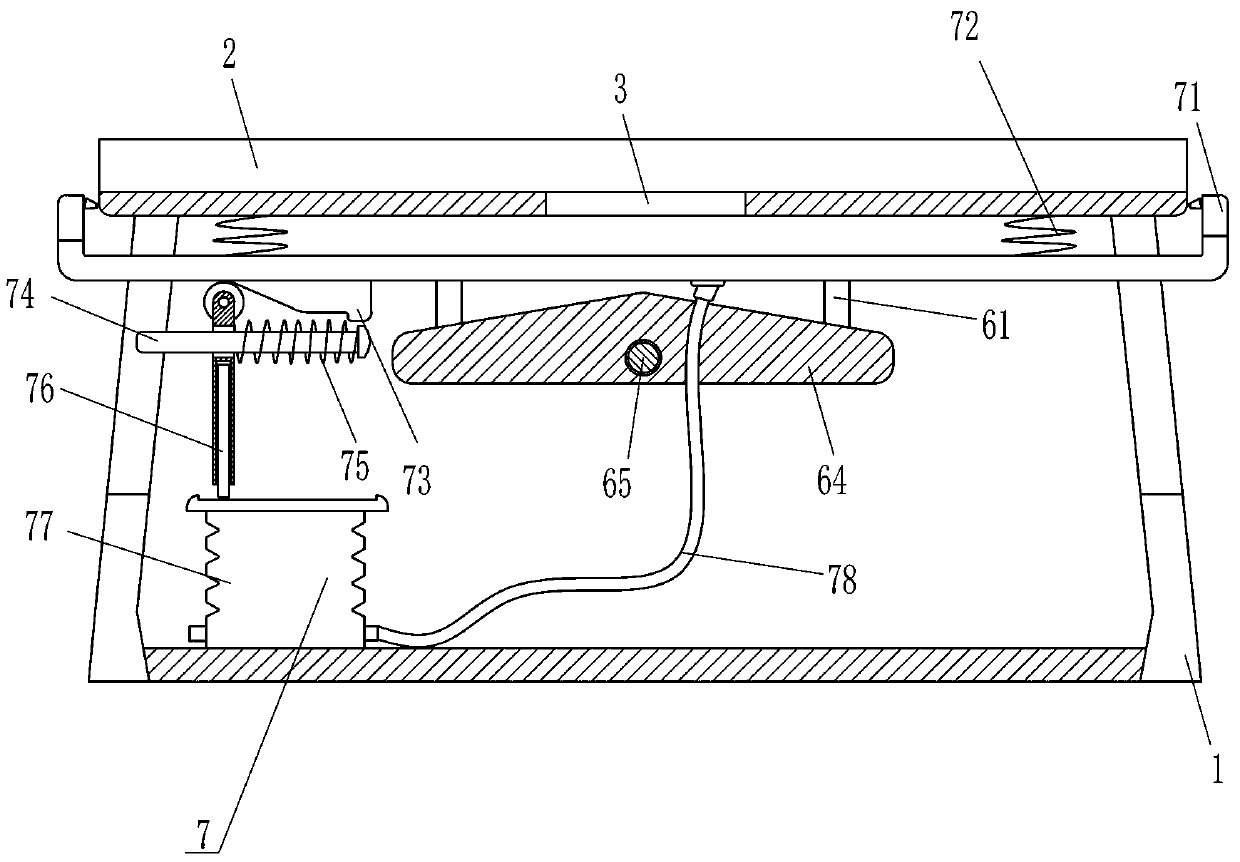
[0021] A steel plate automatic welding mechanical arm, such as Figure 1-5 As shown, it includes a support leg 1, a placement plate 2, a driving mechanism 4, a welding rod clamping mechanism 5 and a steel plate clamping mechanism 6. The support leg 1 is installed at the bottom of the placement plate 2, and the middle part of the placement plate 2 is opened for discharging welding slag. The discharge port 3, the left side of the placement plate 2 is provided with a driving mechanism 4, the moving part of the driving mechanism 4 is provided with an electrode clamping mechanism 5 for clamping the welding rod, wherein the driving mechanism 4 is used to drive the welding rod to clamp Movement of Agency 5.
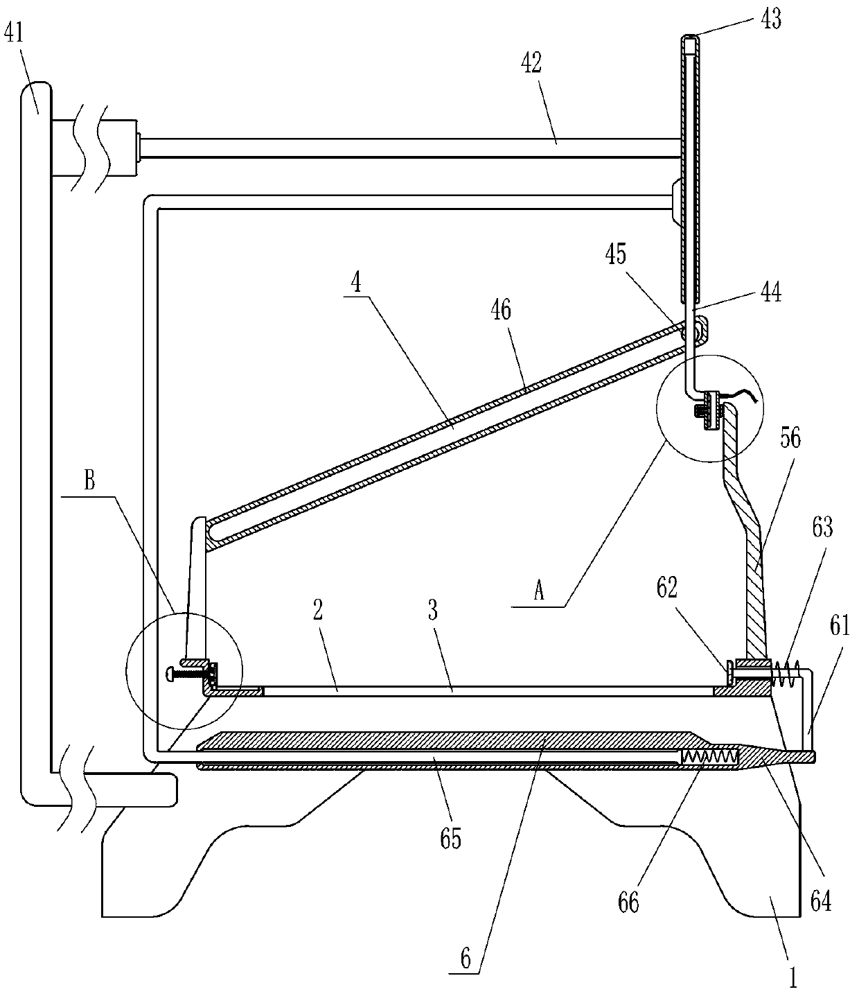
[0022] Driving mechanism 4 comprises mounting plate 41, electric push rod 42, sleeve 43, sleeve bar 44, roller 45 and chute plate 46, and mounting plate 41 is vertically installed in support leg 1, and this mounting plate 41 right side top An electric push rod 42 is installed h...
Embodiment 2
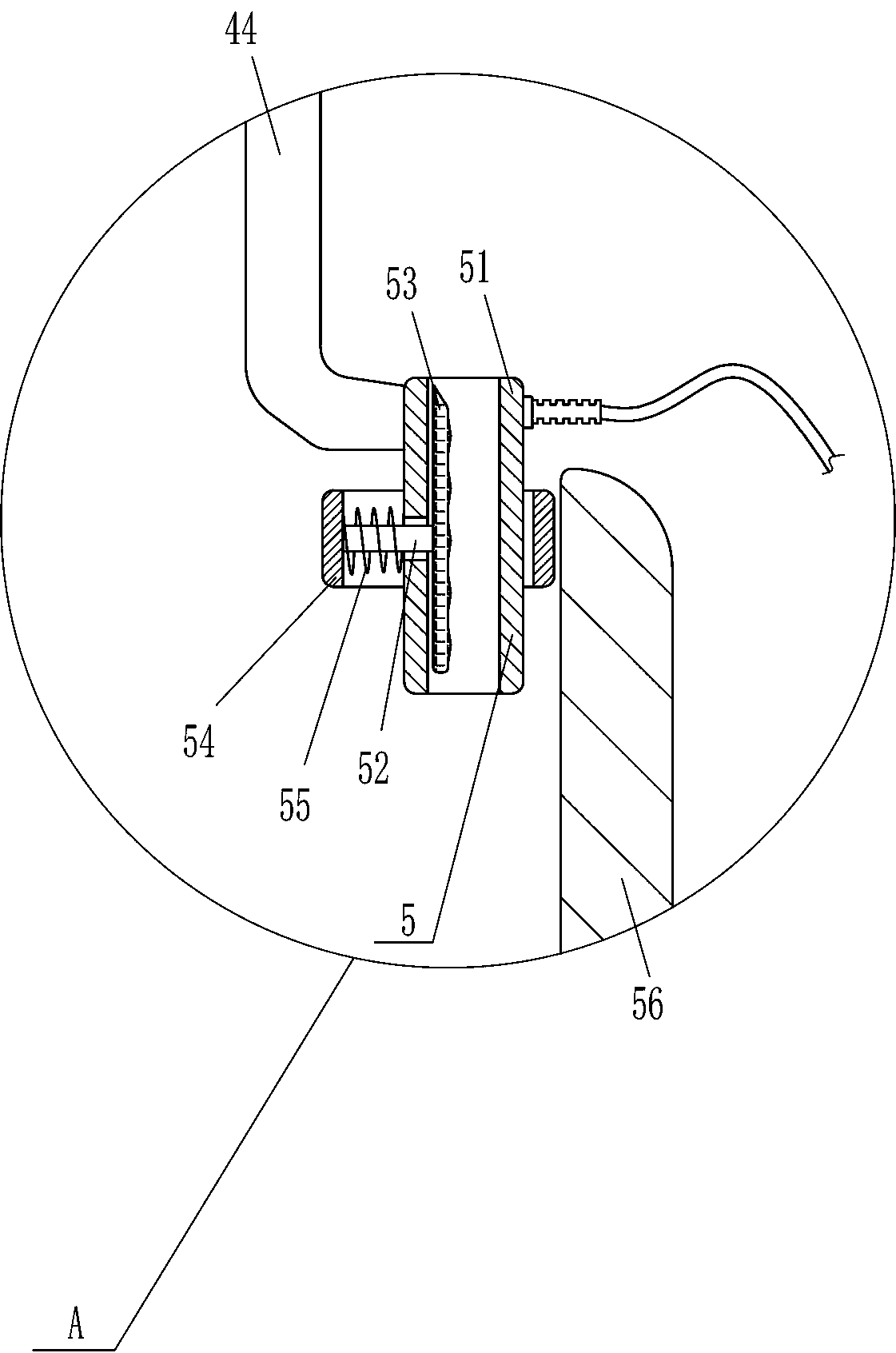
[0026] On the basis of Example 1, such as Figure 1-3 Shown, also comprise steel plate clamping mechanism 6, steel plate clamping mechanism 6 comprises L-shaped rod 61, the second clamping plate 62, the second spring 63, slide plate 64, n-type rod 65 and the 3rd spring 66, place plate 2 There is an L-shaped bar 61 horizontally sliding on the right side. A second splint 62 for clamping the steel plate is installed at the inner end of the L-shaped bar 61. A second spring 63 is connected between the L-shaped bar 61 and the placement plate 2. The bottom end of the L-shaped bar 61 is horizontally equipped with a sliding plate 64, and an n-shaped bar 65 is slidably arranged in the sliding plate 64. A third spring 66 is connected between one end of the n-shaped bar 65 and the sliding plate 64. The n-shaped bar 65 The upper right end is fixedly connected with the sleeve 43 .
[0027] When the sleeve 43 moves to the left, it can drive the n-shaped rod 65 to move to the left, and the n...
Embodiment 3
[0029] On the basis of Example 2, such as Figure 1-5 Shown, also comprise cleaning mechanism 7, and cleaning mechanism 7 comprises porous tube 71, the 4th spring 72, inclined block 73, fixed bar 74, the 5th spring 75, expansion plate 76, inflatable air bag 77 and flexible pipe 78, place The lower part of the plate 2 is provided with a porous tube 71, a fourth spring 72 is connected between the porous tube 71 and the placement plate 2, a slanting block 73 is installed on the rear side of the bottom of the porous tube 71, and a fixed rod 74 is installed horizontally in the leg 1. The fixed rod 74 is slidingly provided with a telescopic plate 76, a fifth spring 75 is connected between the telescopic plate 76 and the fixed rod 74, an inflatable air bag 77 is installed on the leg 1, and a hose is sealed and connected to the inflatable air bag 77. 78, the flexible pipe 78 is sealingly connected with the bottom of the perforated pipe 71.
[0030] It also includes an adjustment plate ...
PUM
 Abstract
Description
Claims
Application Information