Welding auxiliary tool and welding method for instrument installation base

A technology of auxiliary tooling and mounting seat, applied in welding/cutting auxiliary equipment, auxiliary devices, welding equipment, etc., can solve the problems of hand injury in welding, close welding seam distance, difficult to judge and ensure installation accuracy, etc., to prevent hand injury , the effect of extending the distance

Inactive Publication Date: 2019-12-13
GUANGZHOU SHIPYARD INTERNATIONAL LTD
View PDF8 Cites 1 Cited by
  • Summary
  • Abstract
  • Description
  • Claims
  • Application Information

AI Technical Summary

Problems solved by technology

The conventional installation method uses the hand-held mounting base to align with the mounting hole for electric welding positioning. Since it is difficult to observe whether the through hole in the middle of the mounting base is aligned with the mounting hole on the pipe during the welding process, it is difficult to judge during the installation process. And ensure the accuracy of installation
Moreover, since there is no fixing means between the mounting base and the mounting hole on the pipe, the positioning is performed entirely by hand. If the hand holding the mounting base shakes during the installation process, misalignment will occur
In addition, because the length of the instrument mounting seat is generally short, the welding positioning of the mounting seat is carried out by hand-held positioning. The hand holding the mounting seat is too close to the welding seam, which is prone to welding injury.

Method used


Image

  • Welding auxiliary tool and welding method for instrument installation base
  • Welding auxiliary tool and welding method for instrument installation base
  • Welding auxiliary tool and welding method for instrument installation base

Examples


Embodiment Construction

[0034] The technical solutions of the present invention are further described below with reference to the accompanying drawings and through specific embodiments.

[0035] In the present invention, unless otherwise expressly specified and limited, a first feature "on" or "under" a second feature may include the first and second features in direct contact, or may include the first and second features Not directly but through additional features between them. Also, a first feature being "above" a second feature includes that the first feature is directly above and obliquely above the second feature, or simply means that the first feature is at a higher level than the second feature. The first feature being "below" the second feature includes that the first feature is directly below and diagonally below the second feature, or simply means that the first feature is at a lower level than the second feature.

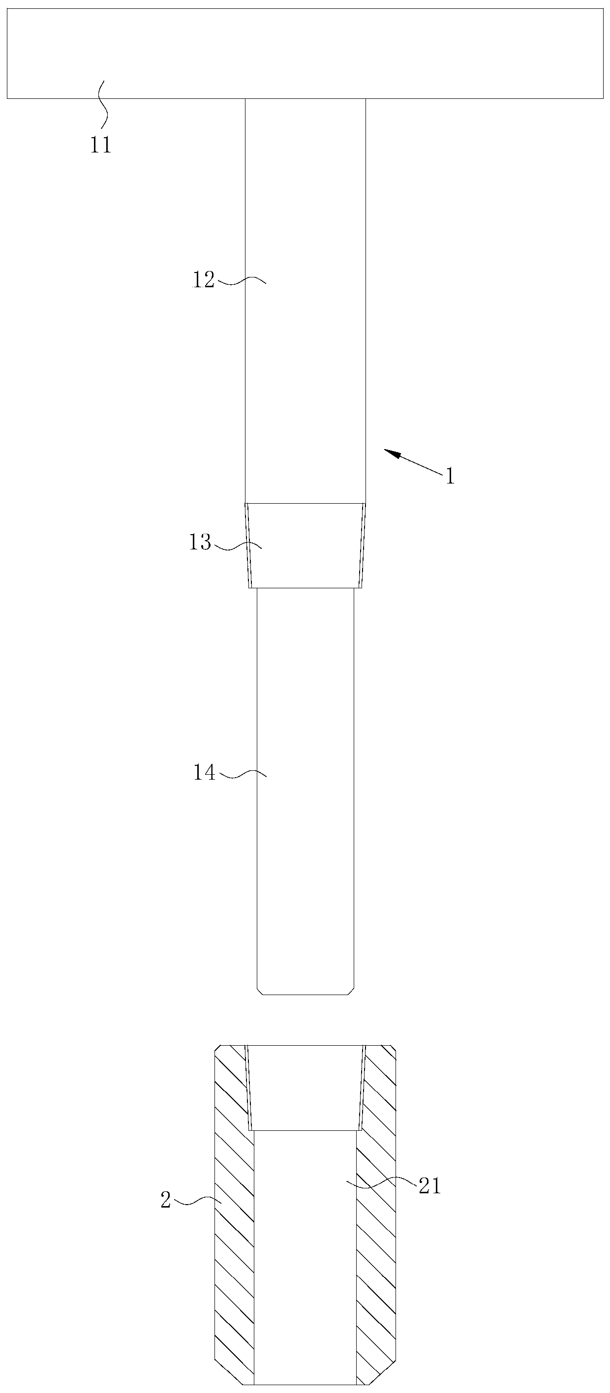
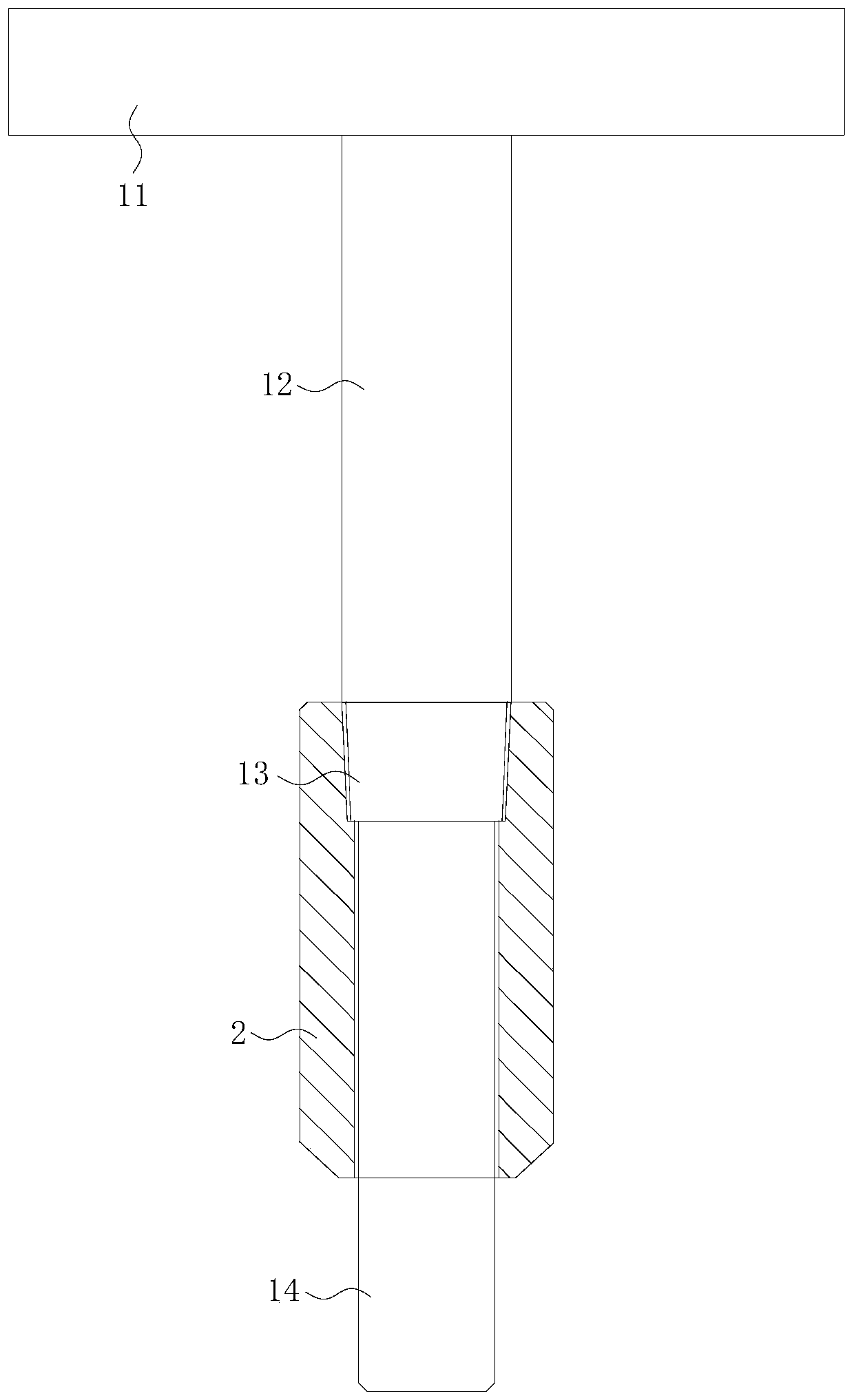
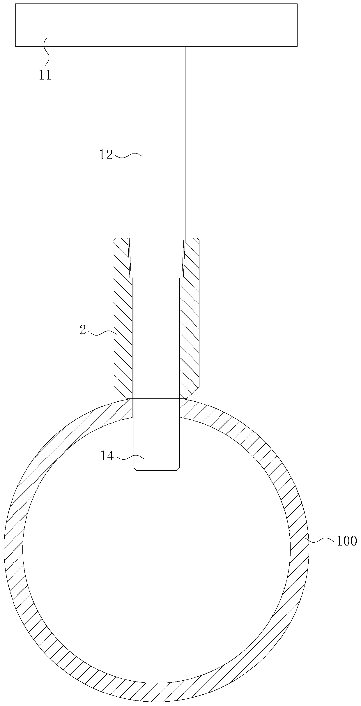
[0036] like Figure 1 to Figure 4 As shown, the welding auxiliary toolin...


PUM

PropertyMeasurementUnit
lengthaaaaaaaaaa

Abstract

The invention discloses a welding auxiliary tool and a welding method for an instrument installation base. The welding auxiliary tool for the instrument installation base comprises a handrail, a connecting rod, a limiting part and a positioning rod, wherein the handrail is perpendicularly connected with the connecting rod; the limiting part is arranged between the connecting rod and the positioning rod; the positioning rod can be inserted into a through hole of the instrument installation base; the limiting part is connected with the instrument installation base; one end, far away from the limiting part, of the positioning rod stretches out of the through hole; and the positioning rod and the instrument installation base keep relative rest. According to the welding auxiliary tool for the instrument installation base provided by the invention, through a restricting effect of the limiting part, the positioning rod stretches out of the through hole of the instrument installation base, sothat the positioning rod can be inserted into an open hole of a pipeline, the instrument installation base is accurately positioned on the open hole of the pipeline, and the through hole in the instrument installation base aligns at the open hole of the pipeline. In addition, through arranging the connecting rod, the distance between a handle and a welding seam is effectively extended, and the occurrence of the phenomenon that a hand is injured in the welding process is prevented.

Description

technical field [0001] The invention relates to the technical field of welding, in particular to a welding auxiliary tool and a welding method for an instrument mounting seat. Background technique [0002] In the pipeline system, in order to achieve local monitoring or remote monitoring of the temperature and pressure of the pipeline system, various instruments such as thermometers, pressure gauges, temperature sensors and pressure sensors need to be installed on the pipeline system. In order to install various instruments such as thermometers, pressure gauges, temperature sensors and pressure sensors on the pipeline, it is generally necessary to weld and install the instrument mounting seat on the pipeline. The instrument mounting base is generally a small metal cylinder with a central through-hole structure, one end of which is fixedly connected to the pipeline by welding, and the other end is detachably connected to the instrument by means of threads. [0003] The key po...

Claims


Application Information

Patent Timeline
Patent Type & Authority Applications(China)
IPC IPC(8): B23K37/053B23K31/02
CPCB23K31/02B23K37/053
Inventor 包霖汪新勇
Owner GUANGZHOU SHIPYARD INTERNATIONAL LTD
Why Eureka
Try Eureka