Arc striking device for ion plating and ion plating device

A technology of ion coating and arc striking device, which is applied in ion implantation coating, sputtering coating, vacuum evaporation coating and other directions, can solve the problems of small magnetic force of coil passing electromagnetic field, sticking hook, easy gas leakage at sealing parts, etc. Save material and strengthen the effect of sealing

Pending Publication Date: 2019-12-13
BEIJING TECHNOL SCI
View PDF0 Cites 3 Cited by
  • Summary
  • Abstract
  • Description
  • Claims
  • Application Information

AI Technical Summary

Problems solved by technology

[0002] In the field of multi-arc ion coating, there are two commonly used arc ignition devices. One is the electric arc ignition device for coil arc ignition. The coil is energized to generate a magnetic field to drive the arc ignition hook to move. After the arc ignition is successful, the coil is powered off and The arc hook is reset by the spring to realize the reciprocating movement of the arc hook. Although this kind of scheme can ensure the sealing, the magnetic field generated by the coil electrification is small, and the spring force matched with it is also small, which not only makes the arc hook The movement stroke is short, and it is very easy to cause the arc hook to stick due to the heating of the arc, resulting in the inability of the arc hook to rebound, resulting in a short circuit; Compressed air, the cylinder shaft drives the arc strike hook to reciprocate. Although this scheme has a long stroke of the arc strike hook and a large power for ion coating, it is not easy to stick the hook, but the seal with the skeleton oil seal is a dynamic seal, and the cylinder shaft Long-term friction with the skeleton oil seal makes the sealing part prone to air leakage and destroys the vacuum in the vacuum chamber

Method used


Image

  • Arc striking device for ion plating and ion plating device

Examples


Embodiment 1

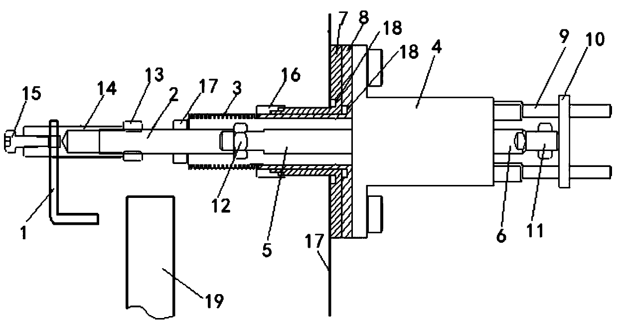
[0032] The invention provides an arc starting device for ion plating and an ion plating device, such as figure 1 As shown, the arc striking device for ion plating in this embodiment includes an arc striking hook 1, a connecting rod 2, a bellows 3, a driving device and a sealing insulator, and a mounting hole is provided on the side wall 20 of the vacuum chamber of the ion plating device , the sealing insulator is used to set and fix in the installation hole and form a sealed connection with the installation hole, the output shaft of the driving device passes through the sealing insulator and is fixedly connected with one end of the connecting rod 2, and the driving device can drive the connecting rod 2 in the axial direction For reciprocating movement, one end of the bellows 3 is fixedly connected with one end of the sealing insulator, the other end of the bellows 3 is fixedly sleeved outside the connecting rod 2 and forms a sealed connection with the connecting rod 2, and the ...

Embodiment 2

[0042] This embodiment provides an ion coating device. The ion coating device in this embodiment includes the arc starting device for ion coating and the vacuum chamber in Embodiment 1. Specifically, the arc starting device for ion coating is fixed in the vacuum chamber. on the side wall 20.


PUM


Abstract

The invention discloses an arc striking device for ion plating and an ion plating device, and relates to the technical field of ion plating. The arc striking device comprises an arc striking hook, a connecting rod, a corrugated pipe, a drive device and a sealing insulating part. A mounting hole is formed in the side wall of a vacuum chamber of the ion plating device, the sealing insulating part isfixed into the mounting hole and connected with the mounting hole in a sealed manner, an output shaft of the drive device penetrates through the sealing insulating part to be fixedly connected with one end of the connecting rod, the drive device can drive the connecting rod to reciprocate in the axial direction, one end of the corrugated pipe is fixedly connected with one end of the sealing insulating part, the other end of the corrugated pipe fixedly sleeves the connecting rod and is connected with the connecting rod in a sealed manner, and the connecting rod penetrates through the corrugated pipe to be fixedly connected with the arc striking hook. The ion plating device comprises the vacuum chamber and the arc striking device for ion plating. The drive device drives the arc striking hook to move, acting force is large, hook adhesion is not easily caused, the corrugated pipe is arranged for static sealing, the sealing performance of the vacuum chamber is good, and vacuum is not easily damaged.

Description

technical field [0001] The invention relates to the technical field of ion plating, in particular to an arc striking device for ion plating and an ion plating device. Background technique [0002] In the field of multi-arc ion coating, there are two commonly used arc ignition devices. One is the electric arc ignition device for coil arc ignition. The coil is energized to generate a magnetic field to drive the arc ignition hook to move. After the arc ignition is successful, the coil is powered off and The arc hook is reset by the spring to realize the reciprocating movement of the arc hook. Although this kind of scheme can ensure the sealing, the magnetic field generated by the coil electrification is small, and the elastic force of the spring matching it is also small, which not only makes the arc hook The movement stroke is short, and it is very easy to cause the arc hook to stick due to the heating of the arc, resulting in the inability of the arc hook to rebound, resultin...

Claims


Application Information

Patent Timeline
Patent Type & Authority Applications(China)
IPC IPC(8): C23C14/32
CPCC23C14/325
Inventor 彭建田琳夏虎
Owner BEIJING TECHNOL SCI
Why Eureka
Try Eureka