Wheel disc type false twist compact spinning device with broken-end breakpoint control function

A compact spinning and breaking point technology, applied in spinning machines, textiles, papermaking, drafting equipment, etc., can solve problems such as increased energy consumption, different yarn forming processes, and different mechanism settings

Pending Publication Date: 2019-12-13
JIAXING UNIV
View PDF3 Cites 2 Cited by
  • Summary
  • Abstract
  • Description
  • Claims
  • Application Information

AI Technical Summary

Problems solved by technology

[0002] Long hairiness of the yarn is usually a harmful defect of the yarn. In order to eliminate the hairiness of the yarn, the current actual production basically uses air flow to gather the fiber bundles before twisting. In the above two types of methods, the airflow method will generate greater energy consumption, and the mechanical method will cause friction; twisting will cause fiber bundles, the false twist technology in the twisting method, and the low twist spinning technology in the ring spindle People have done a lot of research, typical examples are: "Clamping False Twisting Device" proposed in ZL200710089867.9, and the loop dragon belt proposed in ZL 201310091686.5 "Method and Device for Applying False Twist to Yarn Before Ring Spinning" , ZL 201080056636.8 "Ring Spinning Machine with False Twist Device" proposed friction wheels of various structures. These mechanisms are all aimed at the false twist process requirements of low twist spinning. The goal is different, the process is different, the yarn forming process is different, and the mechanism settings are different. The friction type false twist compact spinning proposed by me in the early stage contains two pairs of rollers, the front roller and the lead-out roller. After the hair is generated, it is necessary to remove the fiber strands in time to avoid winding the rollers. If the suction pipes are installed on the jaws of the two rollers, the energy consumption will be increased.

Method used


Image

  • Wheel disc type false twist compact spinning device with broken-end breakpoint control function
  • Wheel disc type false twist compact spinning device with broken-end breakpoint control function

Examples


Embodiment

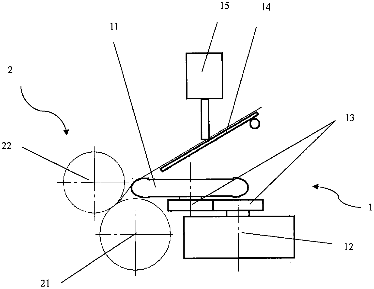
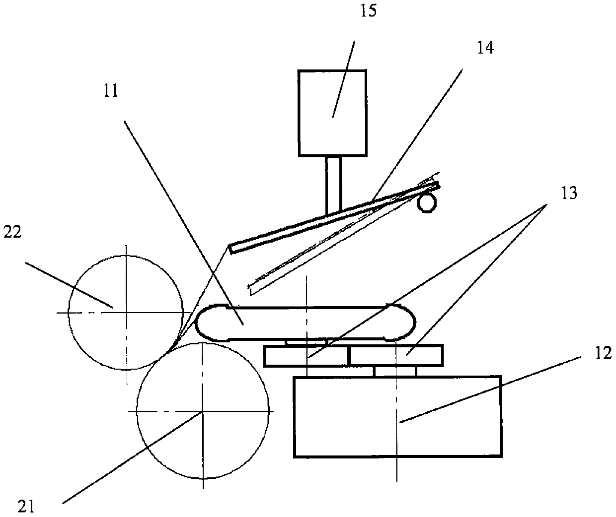
[0015] figure 1 As shown, a wheel-type false-twist compact spinning device 1 with end-break point control is located on the output side of the front roller of the drafting mechanism and the input side of the lead-out roller 2. Each spindle position includes a friction wheel 11. Transmission wheel 12, transmission gear 13, hairiness suppressor 14, breakpoint control mechanism 15, friction wheel 11 and transmission wheel 12 in the device are installed on the base, transmission wheel 12 transmits friction wheel 11 through gear 13, transmission wheel 12 is driven by a transmission belt, the edge of the friction wheel 11 is in contact with the fiber strands, and the friction drives the fiber strands to rotate to form a false twist twist. The broken end break point control mechanism 15 is to control the hairiness suppressor. signal, the breakpoint breakpoint control mechanism rotates the hairiness suppressor ( figure 2 As shown), the plane in contact with the fiber whiskers is def...


PUM


Abstract

The invention relates to a wheel disc type false twist compact spinning device with a broken-end breakpoint control function. Each spindle position of the wheel disc type false twist compact spinningdevice with the broken-end breakpoint control function comprises a friction wheel, a transmission wheel, a base, a hairiness suppressor and a broken-end breakpoint control mechanism. In the device, the friction wheels and the transmission wheels are mounted on the bases, the transmission wheels realize transmission of the friction wheels through gears or shafts, the transmission wheels are drivenby transmission belts, the edges of the friction wheels are in contact with fiber strands, the fiber strands are driven to rotate back through friction to realize false twist, and the broken-end breakpoint control mechanism controls the hairiness suppressor; when a broken-end signal is received, the broken-end breakpoint control mechanism rotates the hairiness suppressor to cause a plane in contact with the fiber strands to deflect relative to a normal spinning position, so that the wrapping angles between the fiber strands and the edges of the friction wheels are reduced, twist of the fiber strands is stopped or the transmission of twist towards a front roller jaw is blocked, and therefore the fiber strands are broken at the front roller jaw.

Description

technical field [0001] The invention belongs to the technical field of ring spinning, and in particular relates to a wheel-type false-twisting compact spinning device with end-break point control. Background technique [0002] Long hairiness of the yarn is usually a harmful defect of the yarn. In order to eliminate the hairiness of the yarn, the current actual production basically uses air flow to gather the fiber bundles before twisting. In the above two types of methods, the airflow method will generate greater energy consumption, and the mechanical method will cause friction; twisting will cause fiber bundles, the false twist technology in the twisting method, and the low twist spinning technology in the ring spindle People have done a lot of research, typical examples are: "Clamping False Twisting Device" proposed in ZL200710089867.9, and the loop dragon belt proposed in ZL 201310091686.5 "Method and Device for Applying False Twist to Yarn Before Ring Spinning" , ZL 201...

Claims


Application Information

Patent Timeline
IPC IPC(8): D01H5/22D01H5/70D01H5/72D01H5/80D01H13/16
CPCD01H5/22D01H5/70D01H5/72D01H5/80D01H13/16
Inventor 陈伟雄
Owner JIAXING UNIV
Why Eureka
Try Eureka