Cast-in-situ bored pile head stirring and crushing device

A technology for bored piles and crushing devices, which is applied to sheet pile walls, buildings, infrastructure projects, etc., can solve the problems of difficult removal of concrete pile heads, high risk of pile head hoisting, and long construction period, saving manpower and material resources. , easy to operate, the effect of reducing the degree of solidity

Pending Publication Date: 2019-12-13
THE FIRST COMPARY OF CHINA EIGHTH ENG BUREAU LTD
View PDF0 Cites 2 Cited by
  • Summary
  • Abstract
  • Description
  • Claims
  • Application Information

AI Technical Summary

Problems solved by technology

[0004] Aiming at the above-mentioned technical problems, the present invention provides a stirring and crushing device fo

Method used


Image

  • Cast-in-situ bored pile head stirring and crushing device
  • Cast-in-situ bored pile head stirring and crushing device
  • Cast-in-situ bored pile head stirring and crushing device

Examples


Embodiment 1

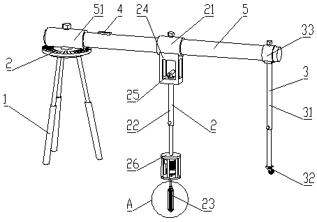
[0038] see figure 1 and figure 2 , the present invention provides a stirring and crushing device for bored cast-in-place pile heads, comprising a tripod 1, and a crossbar 5 horizontally arranged on the upper side of the tripod 1, the top of the tripod 1 is rotatably connected to one end of the crossbar 5, and the other end of the crossbar 5 One end is provided with a vertically downward support assembly 3; the middle part of the cross bar 5 is provided with a vertically downward stirring assembly 2;

[0039] The three supporting legs of the tripod 1 are all telescopic supporting legs;

[0040] The stirring assembly 2 includes a stirring assembly sleeve 21 sleeved in the middle of the cross bar 5 rod body, a vertical stirring main rod 22 is arranged on the lower side of the stirring assembly sleeve 21, and a stirring head 23 is provided at the lower end of the stirring main rod 22;

[0041] The support assembly 5 includes a support main rod 31 arranged below the end of the c...

Embodiment 2

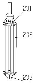
[0067] On the basis of Example 1, different from Example 1, the stirring head 23 includes three integrated upper, middle and lower parts, the upper part 231 and the lower part 233 are conical, and the middle part 232 is a columnar body;

[0068] Both the upper part 231 and the lower part 233 are composed of several inclined rods in a circumferential array, the tip of the upper part 231 is located at the upper end, the tip of the lower part 233 is downward, and several vertical rods are fixedly arranged between the inclined rods of the upper part 231 and the lower part 233, so that Said middle part 232 is made up of said several vertical bar body circle arrays;

[0069] The outer periphery of the junction of the upper part 231 and the middle part 232 and the outer periphery of the junction of the middle part 232 and the lower part 233 are respectively fixed with ring bodies.

[0070] The horizontal bar 5 of this scheme is made of commonly used shelf pipes, with a nominal diamet...


PUM

PropertyMeasurementUnit
Caliberaaaaaaaaaa
Wall thicknessaaaaaaaaaa

Abstract

The invention discloses a cast-in-situ bored pile head stirring and crushing device, and relates to the field of construction equipment. According to the technical scheme, the cast-in-situ bored pilehead stirring and crushing device includes a triangular support and a horizontal bar horizontally arranged on the upper side of the triangular support, one end of the horizontal bar is rotatably connected to the top of the triangular support, and a vertically downward supporting assembly is arranged at the other end of the horizontal bar; a vertically downward stirring assembly is arranged on themiddle part of the horizontal bar; the stirring assembly includes a stirring assembly sleeve connected to the middle part of a bar body of the horizontal bar in a sleeving mode; a vertical stirring main rod is arranged on the lower side of the stirring assembly sleeve, and a stirring head is arranged at the lower end of the stirring main rod; and the supporting assembly includes a supporting mainrod arranged below the end part of the horizontal rod, and a universal wheel is arranged at the bottom end of the supporting main rod. The cast-in-situ bored pile head stirring and crushing device hasthe beneficial effect that since the scheme is implemented in a short time after the completion of cast-in-situ bored pile pouring, the entire construction period is not occupied, and the construction period in which a pile head is removed after the pile head is exposed during traditional earth excavation can be saved.

Description

technical field [0001] The invention relates to the field of construction equipment, in particular to a stirring and crushing device for pile heads of bored piles. Background technique [0002] With the large-scale engineering construction in my country's cities, bored piles are widely used in engineering construction. At present, most of the bored piles are cast-in-place reinforced concrete structures. Due to the construction method, in order to ensure the quality of the pile head, it is necessary to pour a part of concrete more than the pile top elevation required by the design; at the same time, due to poor process control, it is easy to cause overfilling of the pile top concrete. After the foundation pit is excavated to the design elevation, the overfilled concrete pile head needs to be removed. [0003] To sum up, the pile head shall be removed after the excavation of the foundation pit reaches the design elevation. The strength of the pile head is relatively high, an...

Claims


Application Information

Patent Timeline
IPC IPC(8): E02D9/00E02D5/46
CPCE02D5/46E02D9/00
Inventor 刘先观鲁凯崔言继亓祥成王晓宾孔凯杨守兴张宝峰邢朝伟王闵闵许利彤党瑞张树明陈小玮张遇
Owner THE FIRST COMPARY OF CHINA EIGHTH ENG BUREAU LTD
Why Eureka
Try Eureka