
Sheet metal part bending and edge lap joint structure

A technology of sheet metal parts and long folding, applied in the field of sheet metal, can solve problems such as difficult positioning, achieve the effect of convenient welding, overcome elasticity, and facilitate welding work

Pending Publication Date: 2019-12-13
昆山准超五金科技有限公司
View PDF0 Cites 0 Cited by
  • Summary
  • Abstract
  • Description
  • Claims
  • Application Information

AI Technical Summary

Problems solved by technology

[0004] The purpose of the present invention is to provide a sheet metal bending edge structure, which solves the problem of difficult positioning of the sheet metal after bending, and can overcome the elasticity of the folding during welding, which is more conducive to welding

Method used


Image

  • Sheet metal part bending and edge lap joint structure
  • Sheet metal part bending and edge lap joint structure
  • Sheet metal part bending and edge lap joint structure

Examples


Embodiment

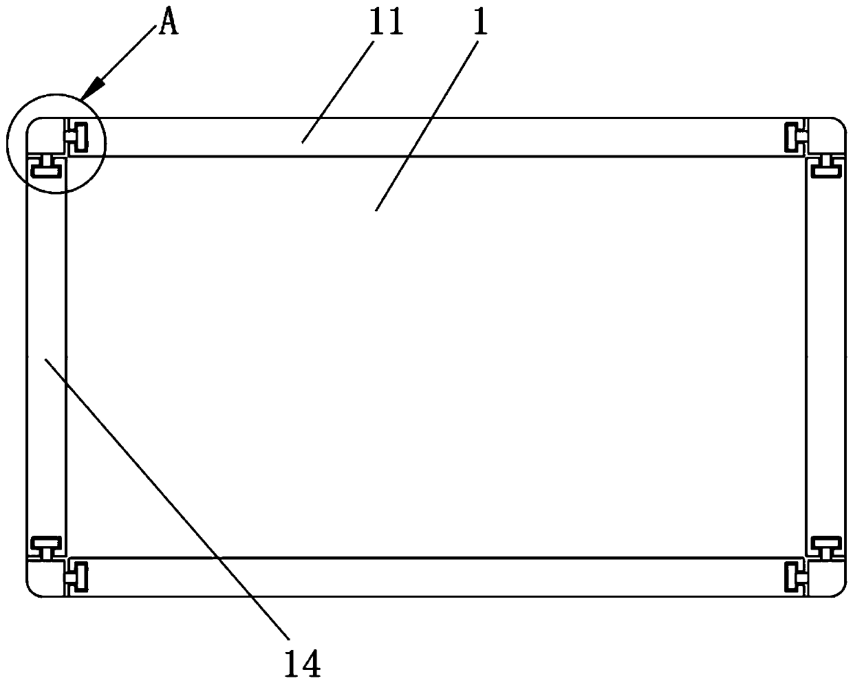
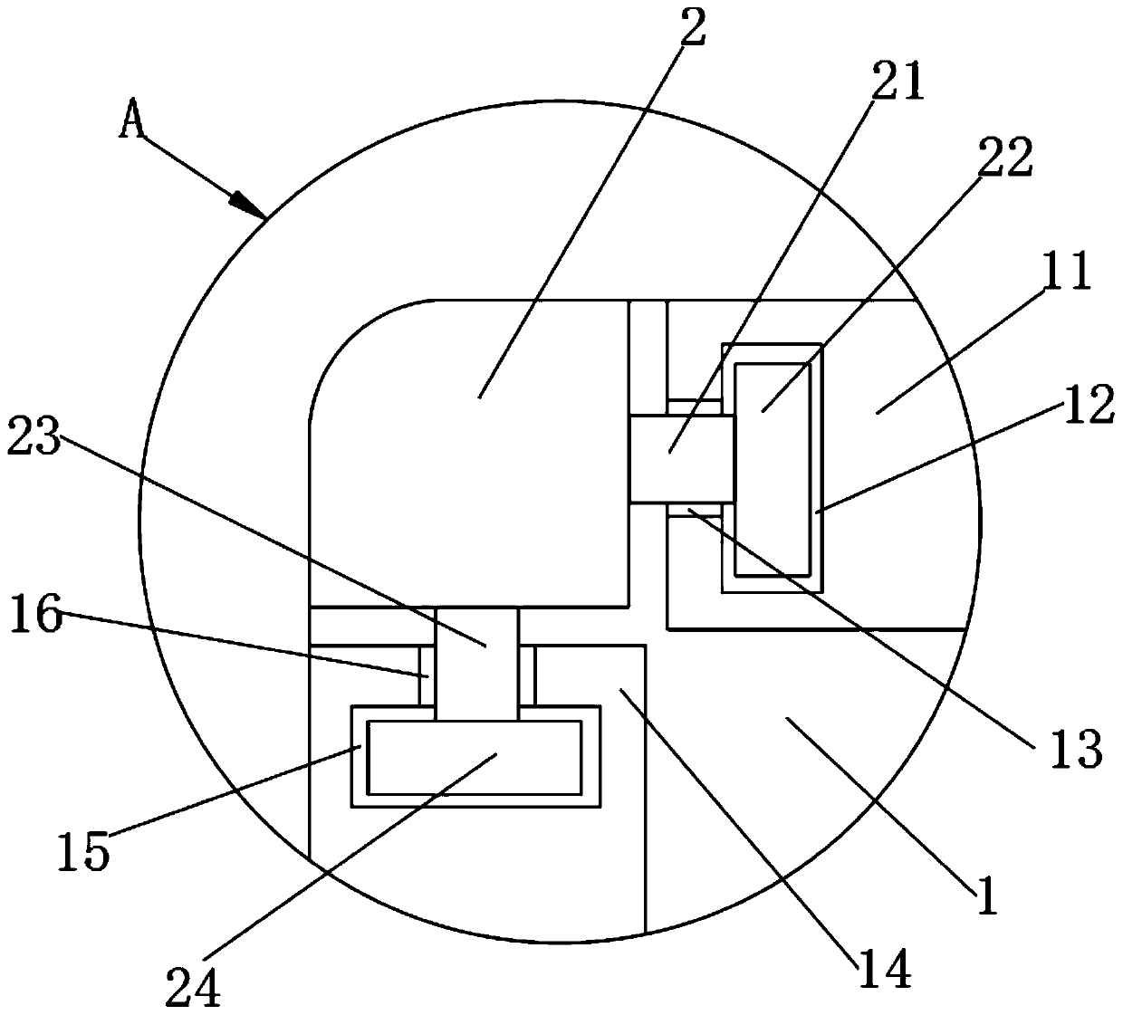
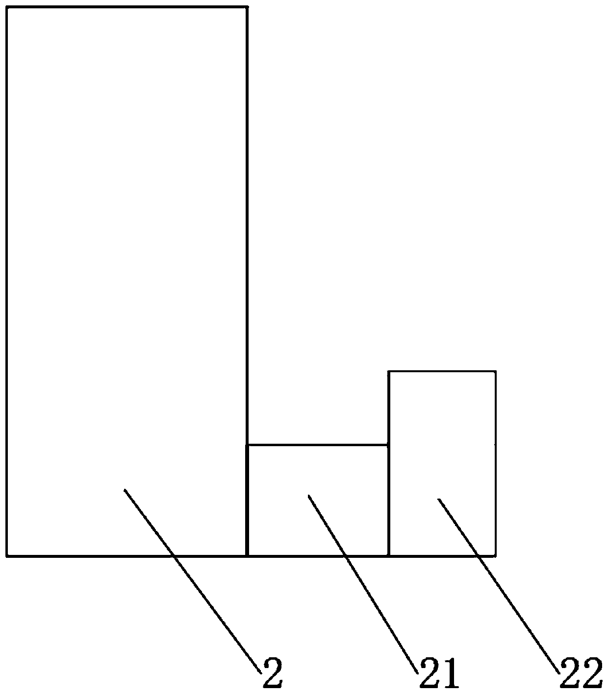
[0022] see figure 1 , figure 2 , a sheet metal bending lap structure, including a cover plate 1, the upper and lower ends of the cover plate 1 are provided with long folds 11, and the long folds 11 are provided with a first clamping groove 12 and a first connecting groove 13, The left and right sides of the cover plate 1 are provided with short folds 14, the short folds 14 are provided with a second card slot 15 and a second connecting groove 16, and the edges of the long folds 11 and the short folds 14 are provided with lap strips 2. The surface of the lapping strip 2 is provided with a first connecting block 21, the end of the first connecting block 21 is provided with a first clamping block 22, the lower end of the lapping strip 2 is provided with a second connecting block 23, and the second connecting block 23 The lower end of the second block 24 is provided.

[0023] see figure 2 , the first clamping slot 12 communicates with the first connecting slot 13 , the first ...


PUM


Abstract

The invention belongs to the field of sheet metal, particularly relates to a sheet metal part bending and edge lap joint structure. The sheet metal part bending and edge lap joint structure comprisesa cover plate. Long folding edges are correspondingly arranged at the upper end and the lower end of the cover plate. A first clamping groove and a first connecting groove are formed in each long folding edge. Short folding edges are arranged on the left side and the right side of the cover plate. A second clamping groove and a second connecting groove are formed in each short folding edge. Lap joint strips are mounted at the edges of the long folding edges and the corresponding short folding edges. First connecting blocks are arranged on the surfaces of the lap joint strips. First clamping blocks are arranged at the tail ends of the first connecting blocks. According to the sheet metal part bending and edge lap joint structure, the lap joint strips are mounted at the combined positions ofthe long folding edges and the short folding edges of the sheet metal, through the match of the first connecting blocks, the first clamping blocks and the first connecting grooves and the first clamping grooves of the long folding edges designed on the lap joint strips, through the match of the second connecting blocks, the second clamping blocks and the second connecting grooves and the second clamping grooves of the short folding edges designed on the lap joint strips, the longing folding edges and the short folding edges are limited conveniently, and welding is more convenient.

Description

technical field [0001] The invention relates to the technical field of sheet metal, in particular to a bending lap structure of a sheet metal part. Background technique [0002] Sheet metal is a comprehensive cold working process for metal sheets, including shearing, punching / cutting / compositing, folding, welding, riveting, splicing, forming (such as car body), etc. Its remarkable feature is that the thickness of the same part is consistent. Products processed by sheet metal technology are called sheet metal parts. The sheet metal parts referred to by different industries are generally different, and are mostly used for assembly. [0003] When processing some sheet metal parts such as box covers, the plates are usually prefabricated, and then folded and welded to form sheet metal parts such as box covers. After the plate is folded, it is very inconvenient to weld and connect the folded edges. Although the existing folded edges are designed with a lapping structure, it is ...

Claims


Application Information

Patent Timeline
IPC IPC(8): F16B7/04
CPCF16B7/0493
Inventor 成志明彭明明成学敏
Owner 昆山准超五金科技有限公司
Learn More