One-way plane torsional spring

A plane torsion spring and torsion spring technology, applied in the field of robotics, can solve the problems of reducing the reliability of the limit function, the failure of the limit cable, and increasing the cost, achieving a large maximum relative rotation range, protecting the structure of the torsion spring, increasing the The effect of deformation space

Active Publication Date: 2019-12-13
HARBIN INST OF TECH SHENZHEN GRADUATE SCHOOL
View PDF22 Cites 4 Cited by
  • Summary
  • Abstract
  • Description
  • Claims
  • Application Information

AI Technical Summary

Problems solved by technology

[0008] The planar torsion spring in the prior art adopts a symmetrical structure in order to meet the requirements of bidirectional deformation. When designing such a planar torsion spring, it is necessary to consider the deformation required by the elastic body during bidirectional deformation and reserve enough deformation space for it. In some special occasions, such as handling equipment, agricultural machinery (rice transplanter, lawn mower), etc., the equipment only needs one-way torque output. When using the flexible structure in the prior art, the symmetrically designed plane torsion The spring will greatly waste the space between the inner and outer rings of the torsion spring, and cannot well meet the requirements of the flexible joint for a large relative rotation angle
[0009] In addition, the planar torsion springs in the prior art often use limit ropes to realize the limit function. Even if the rope is pulled to limit the maximum relative rotation angle of the planar torsion spring, this form depends on the strength of the rope, and the rope is not pulled. The state when stretched (without tension) is not easy to control, and the soft rope may interfere with other structures, making the function of the limit cable invalid and reducing the reliability of the limit function
[0010] In the prior art, the stiffness of the planar torsion spring will change with the relative rotation of the inner and outer rings of the planar torsion spring, the stiffness is not constant, and it is difficult to determine, which increases the difficulty of controlling the torque output of the flexible joint. Meet the actual needs of use; currently, in order to obtain the output torque of the joint, it is necessary to install an expensive torque sensor, which increases the cost and increases the complexity of the structure

Method used


Image

  • One-way plane torsional spring
  • One-way plane torsional spring
  • One-way plane torsional spring

Examples


Embodiment 1

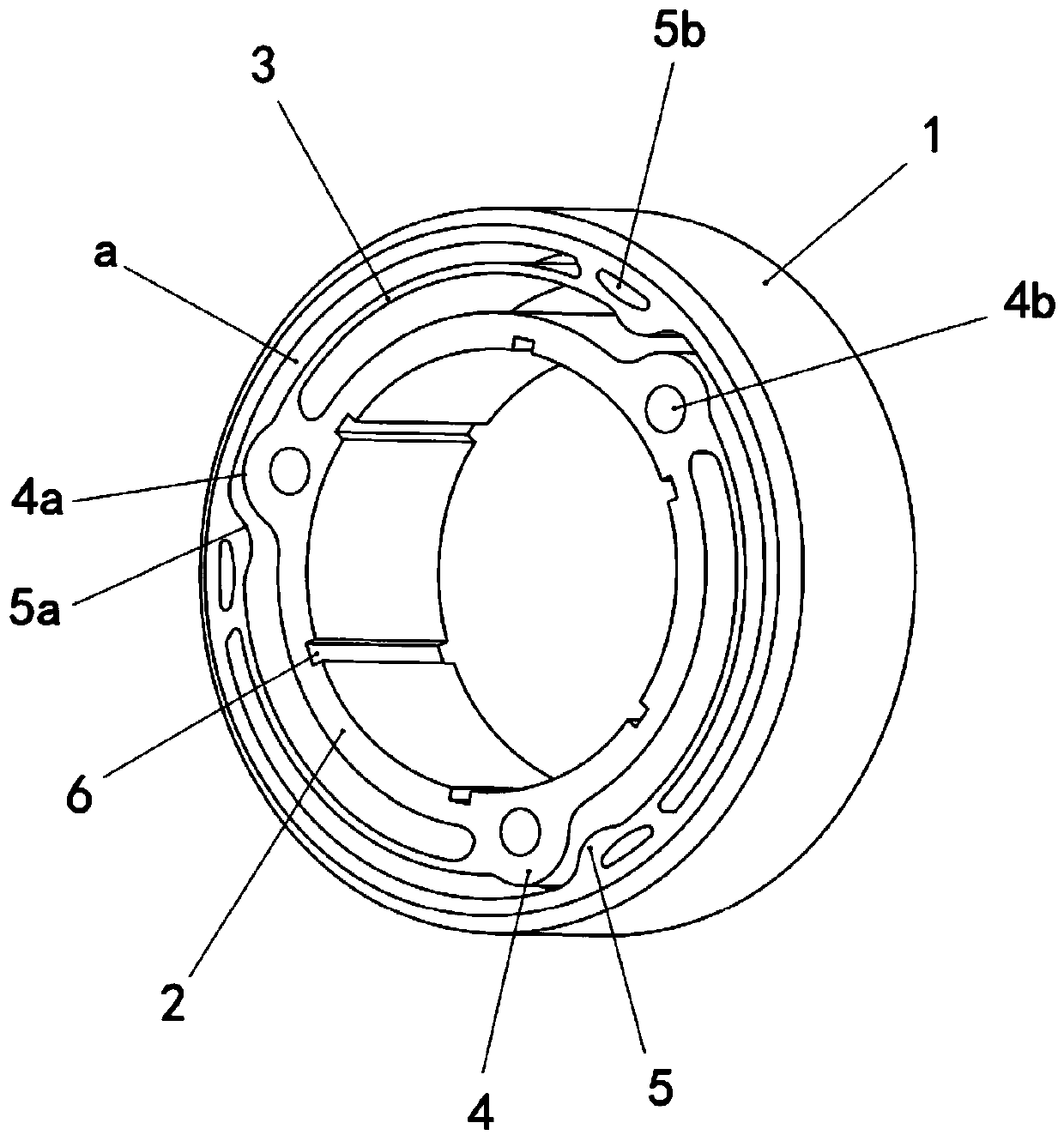
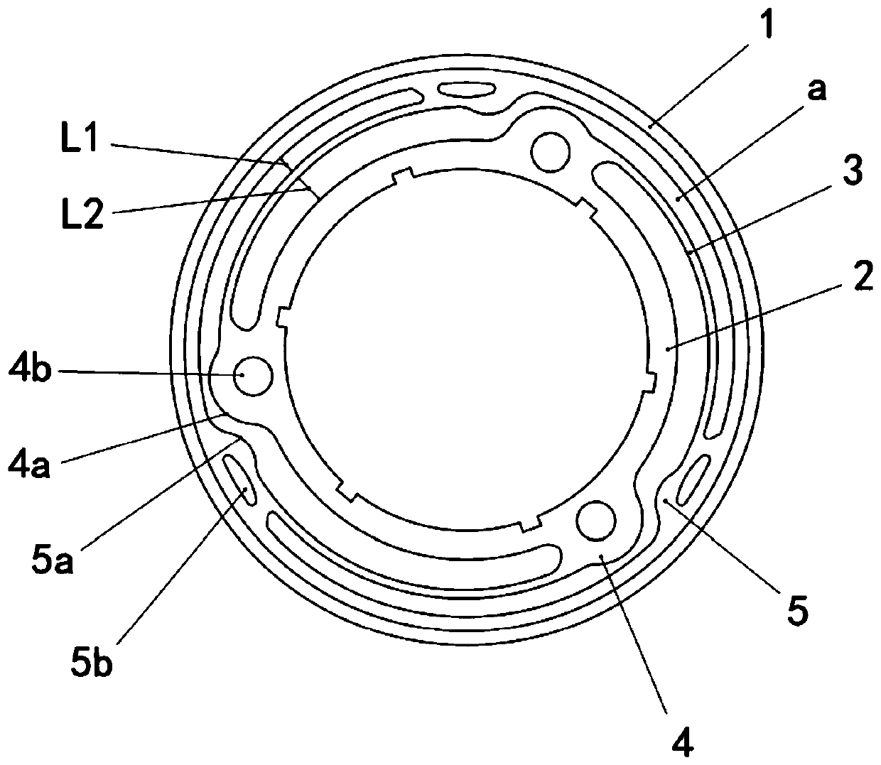
[0037] Such as figure 1 As shown in -5, a one-way planar torsion spring includes a torsion spring outer ring 1, a torsion spring inner ring 2, and a plurality of torsion spring elastic bodies 3, and there is a gap between the torsion spring outer ring 1 and the torsion spring inner ring 2 Space a, a plurality of torsion spring elastic bodies 3 are distributed in the gap space a between the torsion spring outer ring 1 and the torsion spring inner ring 2 .

[0038] One end of the torsion spring elastic body 3 is drawn from the inner peripheral surface of the torsion spring outer ring 1, along the outer peripheral direction of the torsion spring inner ring 2, taking the surrounding curve as the extension reference, and the other end of the torsion spring elastic body 3 extends to the torsion spring inner ring 2, the relative rotation between the torsion spring inner ring 2 and the torsion spring outer ring 1 along the extension direction of the torsion spring elastic body 3 will ...


PUM


Abstract

The invention provides a one-way plane torsional spring. The one-way plane torsional spring comprises a torsional spring outer ring, a torsional spring inner ring and multiple torsional spring elasticbodies. The torsional spring inner ring is located on the inner side of the torsional spring outer ring, a gap exists between the torsional spring outer ring and the torsional spring inner ring, andthe multiple torsional spring elastic bodies are distributed in the gap between the torsional spring outer ring and the torsional spring inner ring, wherein the torsional spring elastic bodies are ledout of the inner peripheral surface of the torsional spring outer ring and are in stretching connection to the outer peripheral surface of the torsional spring inner ring in the outer peripheral direction of the torsional spring inner ring with a surrounding curve as the stretching reference, an abutting portion is arranged on the outer peripheral surface of the torsional spring inner ring, a stopping portion cooperating with the abutting portion is arranged on the inner peripheral surface of the torsional spring outer ring, and the stopping portion is located in front of the forward direction of the tangential directions of the torsional spring elastic bodies. According to the one-way plane torsional spring, on one hand, the one-way relative rotation angle of the torsional spring inner ring and the torsional spring outer ring in the plane torsional spring is increased, on the other hand, the overall rigidity when the torsional spring inner ring and the torsional spring outer ring inthe plane torsional spring rotate relatively is basically unchanged, and the one-way plane torsional spring has the beneficial effects of being simple in structure and high in practicality.

Description

technical field [0001] The invention belongs to the technical field of robots, and in particular relates to a one-way planar torsion spring. Background technique [0002] In recent years, systems for establishing safe interactions between humans and robots have been realized through impedance control, sensor perception, and series elastic actuators. Among them, the joints driven by serial elastics have better impact resistance, which makes the joints flexible in mechanical structure, and are widely used. The main way of this kind of flexible joints is the serial elastic driving form of planar torsion springs, which has Advantages of compact and miniaturized joints. [0003] The flexible joint based on the characteristics of the plane torsion spring relies on the relative rotation of the inner and outer rings and the deformation of the elastic part to realize the flexibility of the joint. The structure of the flexible joint based on the characteristics of the plane torsion ...

Claims


Application Information

Patent Timeline
Patent Type & Authority Applications(China)
IPC IPC(8): F16F1/02B25J17/00
CPCF16F1/027B25J17/00
Inventor 李兵刘一帆宁英豪黄海林徐文福杨晓钧林峰
Owner HARBIN INST OF TECH SHENZHEN GRADUATE SCHOOL
Why Eureka
Try Eureka