
Casting molten metal smelting system and a mounting method thereof

A technology of casting metal and installation method, which is applied in the direction of crucible furnace, furnace, lighting and heating equipment, etc., can solve the problems of damaged furnace lining, inconvenient replacement of crucible, leakage of furnace, etc., so as to ensure the reliability of use, enhance high temperature resistance, The effect of prolonging the service life

Inactive Publication Date: 2019-12-13
GUIZHOU ANJI AVIATION PRECISION CASTING
View PDF8 Cites 0 Cited by
  • Summary
  • Abstract
  • Description
  • Claims
  • Application Information

AI Technical Summary

Problems solved by technology

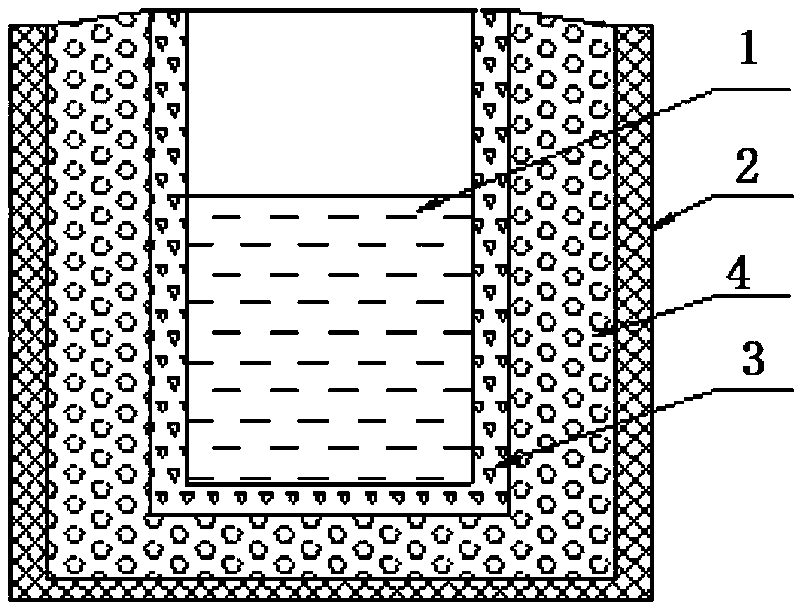
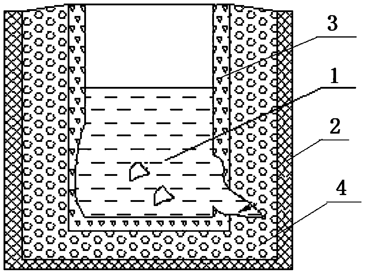
[0002] Smelting molten metal is an important process in the casting process. The structure of the existing casting molten metal smelting system is as follows: figure 1 As shown, it includes a heating device with an open end and a crucible with an open end. The crucible is set inside the heating device and its opening ends are directed in the same direction. A furnace lining is arranged between the outer wall of the crucible and the inner wall of the heating device. Now After repeated use of some casting molten metal smelting systems, the wall of the crucible is gradually burned due to the long-term high temperature of the crucible, and its wall thickness becomes thinner and thinner. When part of the wall of the crucible is burned through, the molten metal It will enter the furnace lining, further damage the furnace lining, and cause leakage, such as figure 2 As shown, and because the crucible wall material and furnace lining material are melted into the molten metal, when it is poured into a casting, it is easy to form slag inclusion defects in the casting. The crucible in the molten metal smelting system needs to be replaced. However, since the crucible wall and furnace lining have been damaged, it is inconvenient to replace the crucible.

Method used


Image

  • Casting molten metal smelting system and a mounting method thereof
  • Casting molten metal smelting system and a mounting method thereof
  • Casting molten metal smelting system and a mounting method thereof

Examples


Embodiment Construction

[0025] The technical solution of the present invention is further described below, but the scope of protection is not limited to the description.

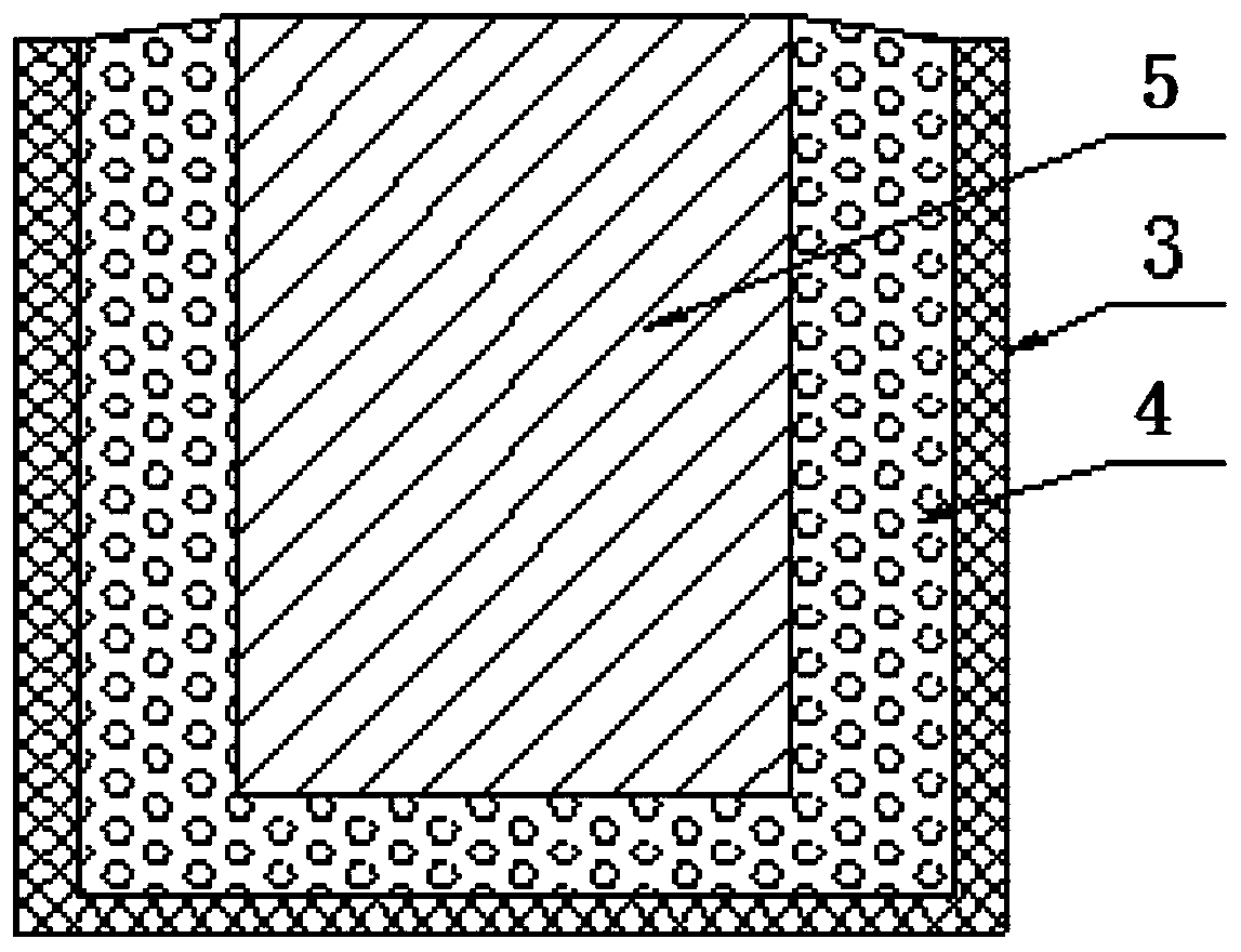
[0026] Such as image 3 , Figure 4 and Figure 5 As shown, the present invention provides a method for installing a casting molten metal smelting system, comprising the following steps:

[0027] Step 1: Provide a heating device 2 with one end open, a crucible 3 with an open end and a granular furnace lining material, and then prepare a crucible mold 5 according to the shape of the crucible 3, so that the shape of the crucible mold 5 is consistent with the crucible 3, and the outline of the crucible mold 5 The difference between the dimension and the outline dimension of the crucible 3 is Δδ, and Δδ is a non-zero positive real number; further, the difference Δδ between the outline dimension of the crucible mold 5 and the outline dimension of the crucible 3 in step 1 is 6mm to 8mm. The pot mold in the preferred step 1 is made of ...


PUM

PropertyMeasurementUnit
Thicknessaaaaaaaaaa

Abstract

The invention provides a casting molten metal smelting system and a mounting method thereof. The mounting method comprises the steps that a crucible mold is prepared, the appearance shape of the crucible mold is consistent with that of a crucible, and the difference between the contour dimension of the shape of the crucible mold and the contour dimension of the shape of the crucible is a non-zeropositive real number; the crucible mold is placed in a heating device, furnace lining material is filled between the crucible mold and the heating device, the crucible mold is taken out, the cruciblemold is put into the crucible, and then refractory sand is filled between the crucible and a furnace lining; the casting molten metal smelting system comprises the heating device with an opening at one end and the crucible with an opening at one end, the crucible is sleeved in the heating device, the direction of the opening end of the crucible and the direction of the opening end of the heating device are consistent, and a refractory layer and the furnace lining are sequentially arranged between the outer wall of the crucible and the inner wall of the heating device from inside to outside. Byadopting the technical scheme, the furnace lining and the crucible are isolated through the refractory layer, burning damage caused to the furnace lining can be prevented after the crucible is damaged, the phenomenon of furnace leakage is avoided, the service life of the casting molten metal smelting system is prolonged, and the operation of replacing the new crucible is convenient.

Description

technical field [0001] The invention relates to the technical field of casting technology, in particular to a casting molten metal smelting system and an installation method thereof. Background technique [0002] Smelting molten metal is an important process in the casting process. The structure of the existing casting molten metal smelting system is as follows: figure 1 As shown, it includes a heating device with an open end and a crucible with an open end. The crucible is set inside the heating device and its opening ends are directed in the same direction. A furnace lining is arranged between the outer wall of the crucible and the inner wall of the heating device. Now After repeated use of some casting molten metal smelting systems, the wall of the crucible is gradually burned due to the long-term high temperature of the crucible, and its wall thickness becomes thinner and thinner. When part of the wall of the crucible is burned through, the molten metal It will enter th...

Claims


Application Information

Patent Timeline
IPC IPC(8): F27B14/08F27D1/00
CPCF27B14/08F27B2014/0825F27B2014/0843F27D1/0033
Inventor 潘年峰冉兴张宁
Owner GUIZHOU ANJI AVIATION PRECISION CASTING
Learn More