
Servo driver and servo drive system

A servo drive and servo drive technology, applied in general control systems, control/adjustment systems, instruments, etc., can solve problems such as poor reliability of data communication and unsatisfactory data frame transmission speed, so as to solve communication obstacles and improve data transmission rate Effect

Active Publication Date: 2019-12-13
SHANGHAI ELECTRICGROUP CORP
View PDF12 Cites 2 Cited by
  • Summary
  • Abstract
  • Description
  • Claims
  • Application Information

AI Technical Summary

Problems solved by technology

[0004] The technical problem to be solved by the present invention is that the servo driver in the prior art has defects such as unsatisfactory data frame transmission speed and poor data communication reliability, and the purpose is to provide a servo driver and a servo drive system

Method used


Image

  • Servo driver and servo drive system
  • Servo driver and servo drive system
  • Servo driver and servo drive system

Examples


Embodiment 1

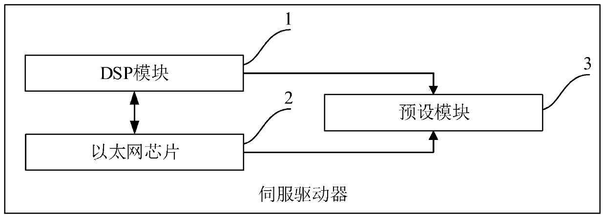
[0046] Such as figure 1 As shown, the servo driver of this embodiment includes a DSP module 1 , an Ethernet chip 2 and a preset module 3 .

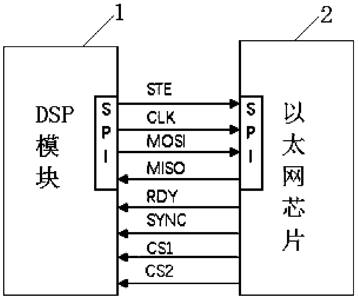
[0047] The communication connection between the DSP module 1 and the Ethernet chip 2 is carried out through the SPI interface;

[0048] Wherein, the DSP module 1 corresponds to the first communication protocol, and the Ethernet chip 2 corresponds to the second communication protocol;

[0049] Specifically, the DSP module 1 may use a TMS320F2809 chip, or other chips such as DSP28 series. Wherein, the communication protocol adopted by the DSP module 1 is the Modbus protocol.

[0050] Ethernet chip 2 is a chip supporting EtherCAT communication function, such as XMC4300 chip, or combination of STM32 chip and ET1100 chip, combination of STM32 chip and ET1200 chip, combination of DSP and ET1100 chip, combination of DSP and ET1200 chip, etc. Among them, the XMC4300 chip integrates the functions of the STM32 chip (or DSP) and ET1X00, and the X...

Embodiment 2

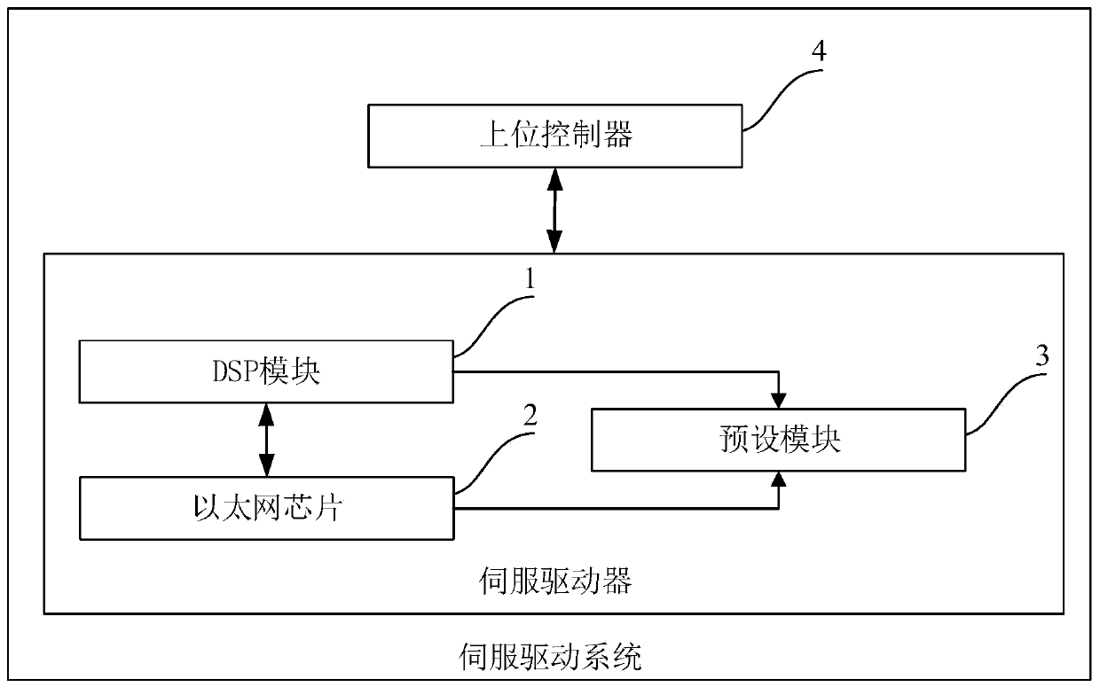
[0072] Such as image 3 As shown, the servo drive system in this embodiment includes the servo drive in Embodiment 1, and the servo drive system also includes a host controller 4 .

[0073] The host controller 4 communicates with the Ethernet chip 2;

[0074] During EtherCAT communication transmission, the Ethernet chip 2 acts as the master station, and the DSP module 1 acts as the slave station. The master station is used to send request data to the slave station, and the slave station is used to send the required data to the slave station.

[0075] The data transmission between DSP module 1 and Ethernet chip 2 follows the requirement that a command (request or response) corresponds to a data value, wherein the length of the command and data is 1 word, and the upper two bits in the command word are the command The type (request or response), the lower 14 bits of the command word is the address value, see the following table for details:

[0076]

[0077] During EtherCAT ...


PUM


Abstract

The invention discloses a servo driver and a servo driving system. The servo driver comprises a DSP module, an Ethernet chip and a preset module; the DSP module and the Ethernet chip are connected incommunication connection through an SPI interface; the preset module is used for presetting a corresponding relationship between an address in a first communication protocol and a variable name in a second communication protocol; before SPI data transmission, the Ethernet chip is used for converting the data length of the variable data to be transmitted into a set length; and when SPI data transmission is carried out, the Ethernet chip is used for sending the variable data with the set length to the DSP module according to the address. According to the system, the SPI data transmission betweenthe DSP module and the Ethernet chip is realized by realizing the corresponding relationship between the preset communication protocols, the problem of communication obstacles between the Modbus protocol and the CoE protocol is solved, and the data transmission rate is improved by adopting a full duplex data transmission mode.

Description

technical field [0001] The invention relates to the technical field of industrial automation, in particular to a servo drive and a servo drive system. Background technique [0002] With the rapid development of industrial automation and the strong real-time and expansibility advantages of EtherCAT (Ethernet Control Automation Technology) fieldbus, more and more servo drives (such as AC servo drives) are also equipped with EtherCAT communication functions. [0003] At present, the communication between the DSP (Digital Signal Processing) unit and the FPGA (Field Programmable Logic Gate Array) unit is generally realized by using the SPI serial port connection in the servo driver; among them, the DSP adopts TMS320F28335, and the FPGA adopts the EtherCAT industrial Ethernet chip ET1200 , the SPI serial port in this communication method sends the address and data separately, and at the same time, the reading and writing are also performed asynchronously, which seriously affects t...

Claims


Application Information

Patent Timeline
IPC IPC(8): G05B19/042
CPCG05B19/0423
Inventor 张静
Owner SHANGHAI ELECTRICGROUP CORP
Learn More