Modification method suitable for electron accelerator equipment based on cobalt source radiation shielding device

A technology for electron accelerators and shielding devices, applied in irradiation devices, nuclear engineering, etc., can solve problems such as potential safety hazards, achieve low installation costs, increase the scope of application, and reduce costs

Active Publication Date: 2021-09-03
天津市技术物理研究所有限公司
View PDF0 Cites 0 Cited by
  • Summary
  • Abstract
  • Description
  • Claims
  • Application Information

AI Technical Summary

Problems solved by technology

[0002] The cobalt source radiation shielding device is a place for storing cobalt-60 radioactive sources. It is used to irradiate food, medicine, polymer materials, etc. to achieve the purpose of disinfection and material modification. It is made of steel and cement, which can achieve the effect of shielding the gamma rays of the cobalt-60 radioactive source. During use, because the cobalt-60 radioactive source continuously releases rays and decays continuously, the cobalt source irradiation factory needs to purchase it every one to two years. Cobalt-60 radioactive sources are supplemented. For the sake of safety, the supervision and approval of cobalt-60 radioactive sources by the environmental protection department is becoming increasingly strict. In addition, some small and medium-sized cobalt source irradiation devices have certain safety hazards in the irradiation mechanical design. The purchase of cobalt-60 radioactive sources is subject to various restrictions, and even faces the situation of shutting down

Method used


Image

  • Modification method suitable for electron accelerator equipment based on cobalt source radiation shielding device
  • Modification method suitable for electron accelerator equipment based on cobalt source radiation shielding device
  • Modification method suitable for electron accelerator equipment based on cobalt source radiation shielding device

Examples


Embodiment 1

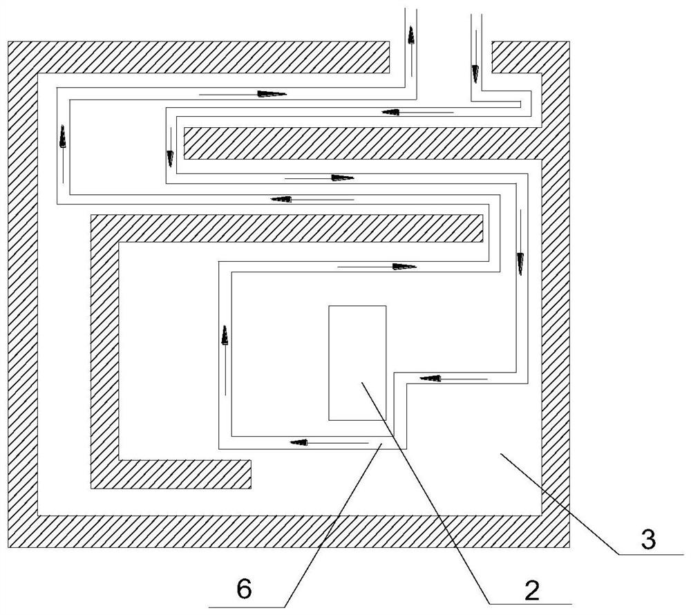
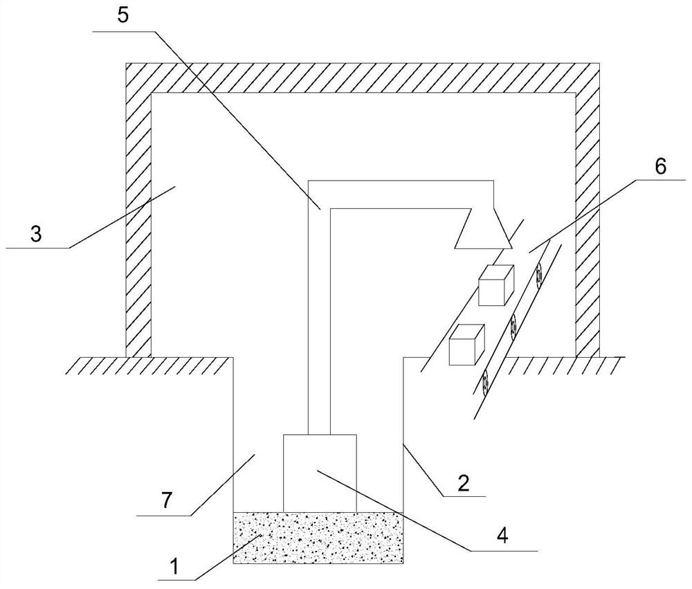
[0033] A modification method suitable for electron accelerator equipment based on a cobalt source radiation shielding device, comprising the following steps, step (1): using building materials 1 to partially fill the cobalt source water well 2, so that radiation is formed in the cobalt source water well 2 The cavity 7 and the cobalt source water well 2 are provided with a cobalt source irradiation chamber 3; step (2): the linear electron accelerator is fixed at the bottom of the cobalt source water well 2 or fixed and suspended in the irradiation cavity 7 via a steel plate, And the scanning window 5 is installed at the free end of the linear electron accelerator, and the scanning window 5 installed extends into the cobalt source irradiation chamber 3; Step (3): a conveying device 6 is provided on the ground, and the conveying device 6 is arranged along the The side wall of the cobalt source irradiation chamber 3 is set, and the scanning window 5 is located above the conveying d...

Embodiment 2

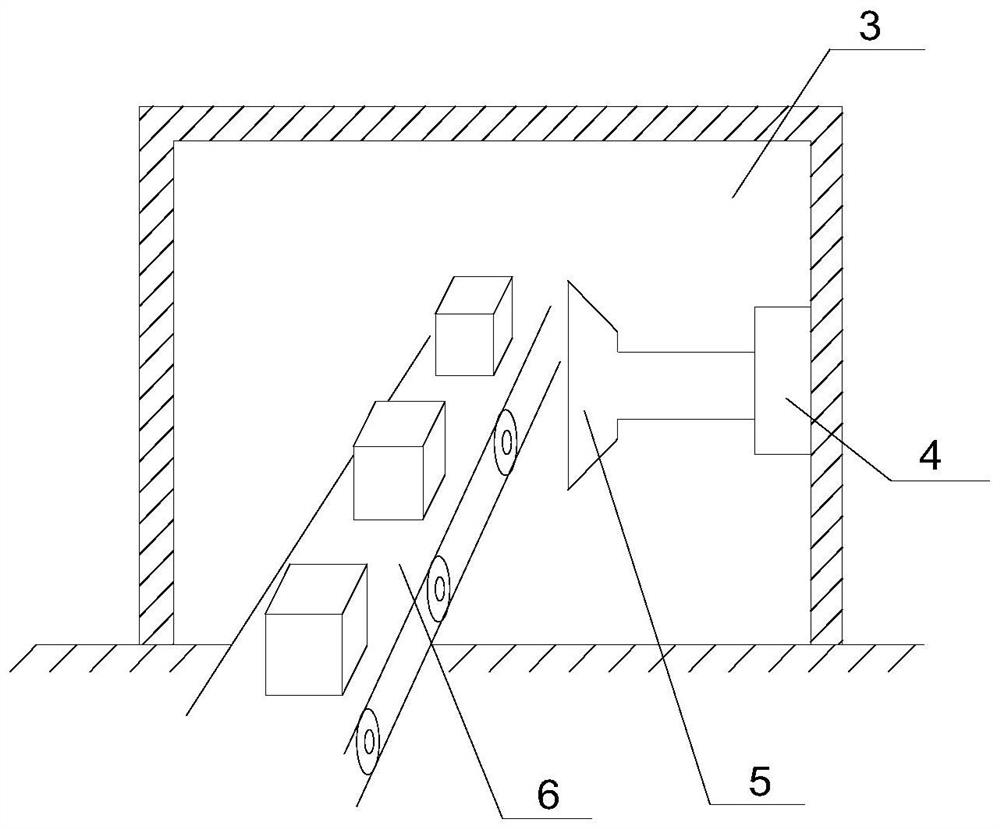
[0035] A modification method suitable for electron accelerator equipment based on a cobalt source radiation shielding device, comprising the following steps, step (1): use building materials 1 to fully fill the cobalt source water well 2, and set the cobalt source water well 2 with cobalt Source irradiation chamber 3; step (2): the linear electron accelerator is vertically fixedly installed on the inner wall of the cobalt source irradiation chamber 3, and a scanning window 5 is installed at the free end of the linear electron accelerator; step (3): on the ground A conveying device 6 is arranged on the top, and the conveying device 6 is arranged along the side wall of the cobalt source irradiation chamber 3, and the conveying direction of the conveying device 6 is perpendicular to the central axis of the scanning window 5, that is, the scanning window 5 is located on the conveying device. 6 side ends, such as image 3 The schematic diagram of the structure of the modified linea...

Embodiment 3

[0037] A modification method suitable for electron accelerator equipment based on a cobalt source radiation shielding device, comprising the following steps, step (1): use building materials 1 to fully fill the cobalt source water well 2, and set the cobalt source water well 2 with cobalt Source irradiation room 3; step (2): fixedly install the plum petal type electron accelerator on the top of the outer wall of the cobalt source irradiation room 3, and add a first shielding room 8 outside the plum petal type electron accelerator, and place the plum petal type electron accelerator The free end of the electron accelerator extends to the inside of the cobalt source irradiation chamber 3 and a scanning window 5 is installed; step (3): a conveying device 6 is provided on the ground, and the conveying device 6 is arranged along the cobalt source irradiation chamber 3 The side wall is set, and the scanning window 5 is located above the conveying device 6, such as Figure 4The schema...


PUM


Abstract

The invention provides a transformation method suitable for electron accelerator equipment based on a cobalt source radiation shielding device, comprising the following steps: Step (1): filling the cobalt source water well with building materials, and covering the cobalt source water well with the cobalt source Irradiation room; step (2): the electron accelerator is fixed, and the electron accelerator is fixedly installed on the cobalt source irradiation room or the cobalt source water well in the step (1), and a scanning window is installed at the free end of the electron accelerator ; Step (3): a transmission device is provided on the ground, the transmission device runs through the side wall of the cobalt source irradiation chamber, and the scanning window is aligned with the transmission device. The present invention utilizes the original cobalt The shielding function of the source irradiation device transforms it into the workplace of the electron accelerator, so that the original cobalt source irradiation enterprises can continue to engage in the irradiation processing industry, and solve the transformation problem of the cobalt source irradiation processing enterprises at the lowest cost. The problem of secondary utilization of the cobalt source irradiation device is solved.

Description

technical field [0001] The invention belongs to the technical field of transformation of radiation shielding devices, and in particular relates to a transformation method suitable for electron accelerator equipment based on cobalt source radiation shielding devices. Background technique [0002] The cobalt source radiation shielding device is a place for storing cobalt-60 radioactive sources. It is used to irradiate food, medicine, polymer materials, etc. to achieve the purpose of disinfection and material modification. It is made of steel bars and cement, which can achieve the effect of shielding the gamma rays of the cobalt-60 radioactive source. During use, because the cobalt-60 radioactive source continuously releases rays and decays continuously, the cobalt source irradiation factory needs to purchase it every one to two years. Cobalt-60 radioactive sources are supplemented. For the sake of safety, the supervision and approval of cobalt-60 radioactive sources by the env...

Claims


Application Information

Patent Timeline
Patent Type & Authority Patents(China)
IPC IPC(8): G21K5/10
CPCG21K5/10
Inventor 杨国祥杨斌张玥靳健乔唐卫东郭红旗王崇林
Owner 天津市技术物理研究所有限公司
Why Eureka
Try Eureka